
Official websites use .gov
A .gov website belongs to an official government organization in the United States.
Secure .gov websites use HTTPS
A lock (
) or https:// means you’ve safely connected to the .gov website. Share sensitive information only on official, secure websites.
Closed Cycle Refrigerators (CCR)
| System Description | Temperature Range(K) | Other Capabilities | Available Instruments |
|---|---|---|---|
| Low T Low Power CCRs | 6-325 | High Voltage (6kV) | All |
| Low T High Power CCRs | 3 - 325 | Electromagnet Mountable | All except HFBS |
| High T High Power CCRs | 14 - 800 | High Voltage(6KV) | All except HFBS |
| Top Loading CCR | 5-700 | Gas Handling, High Pressure | All |
General CCR Information
How They Work
- Our CCRs use the Gifford-McMahon Refrigeration Scheme
- Helium gas is the refrigerant
- The gas compressor (operating near room temperature) and the cryogenic expansion cylinder (cold head) are thermally linked by a regenerator or thermal storage device
- The gas is driven through the 4-step cycle shown below
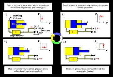
-
Temperature Sensors
Tempeature sensors are a standard item in the CCR systems. Silicon diode DT670 sensor is the most common and is used for low temperature measurements. Platinum sensor is used for high temperature measurements. Cernox sensors are used for CCR tails in magnetic fields. Thermocouples are sometimes used in rare cases. Temperature sensor information for individual systems is available in the booklet attached to each system. The information includes the type, temperature range, corresponding controller curve and physical location. Be sure to verify this information before starting the system. -
Temperature Controllers
These are another standard piece of the CCR system. We use Lakeshore 340/331/335/336 controllers on all of the systems and they all use identical cabling. This allows us to easily diagnose problems and have plenty of spare parts on hand. The main difference between these controllers is that the 340/336 can supply 2 amps of heater output and the 331/335 can supply only 1 amp. For this reason the 340/336 are used on all of the high temperature systems which require more heater power. Be sure to verify that all sensors are reading at room temperature and contact a sample environment team member if you have problems. -
Sample Space and Sample Mounting
-

CCR sample mounting geometry for ARS CCRs -

CCR sample mounting geometry for Janis CCRs - Sample Mounting Info Page
-
-
PID Parameters
In general PID parameters should be determined and loaded into the controller before a CCR system is put into service. However, sometimes parameters get changed by users and are not returned to the standard values. Double check that PID values are correct by comparing those stored in the controller with those in the system manual.
Note: These new PID values take advantage of a feature called a PID zone table. Below you will find a link to a one page manual on how to load a PID zone table.
Setup
Many of the different items that make up the CCR systems are standard and interchangable among the different systems, somtimes even the different types of systems. These items include the sample block, heat shield cans, temperature controller, sensor and heater cables and vacuum can. New systems are generally bought to conform to the standard setup to make integration easier. This also makes going in-between the different systems easier for experienced and novice users. Another important aspect of a CCR system are PID parameters. These parameters vary depending on the setup of each type of CCR and sometimes even on the exact system in use.
Contacts:
- tanya.dax [at] nist.gov (Tanya Dax)
- qiang.ye [at] nist.gov (Qiang (Alan) Ye)
Contacts
-
(301) 975-5295