
Official websites use .gov
A .gov website belongs to an official government organization in the United States.
Secure .gov websites use HTTPS
A lock (
) or https:// means you’ve safely connected to the .gov website. Share sensitive information only on official, secure websites.
BT-8 Ancillary Equipment
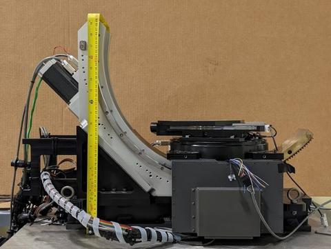
Sample stage
Two stages for sample positioning and sample orientation will be installed: Small to medium weight samples (<10 kg) are mounted on a large phi-chi goniometer with custom XYX-table. The large goniometer eliminates the need for sample remounting and the table can be used as a sample changer for high-throughput texture measurements. Large samples up to 250 kg weight can measured using the base XYZ-table after removing the top goniometer.
Uniaxial load frame
The uniaxial load frame has a capacity of 100 kN with the possibility of using custom grips to accommodate specimen shapes and materials for which standard grips may not be feasible.
Multi-axial loading devices
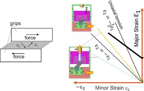
Sheet metal forming is generally comprised of multi-axial straining modes that often occur in combinations or path changes, i.e. one mode of deformation up to a certain strain is followed by a different mode. A frequently occurring example for a path change is bi-axial stretching (such as deep drawing a beverage can), followed by bending (forming a hem) which is best described as plane-strain deformation.
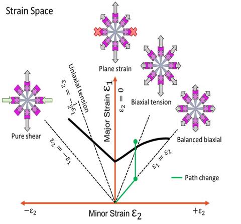
Different straining modes and strain path change. The solid black curve is the forming limit (maximum possible strains).
It is a key property of multi-axial deformation that it cannot be simply derived from sequential combinations of uniaxial straining in different direction, therefore requiring the direct measurement. While multi-axial strains can be measured using optical methods the same is not true for the stresses where diffraction is emerging as the most promising measurement method.
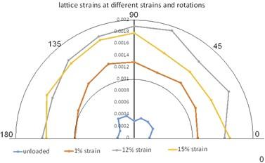
Evolution of yield stresses with strain in multi-axial deformation.
Fracture strain estimates and elastic spring-back calculations require the knowledge of the yield function (stress-strain function) at every point along the deformation path. Such operations have in common that the necessary stress data cannot be obtained from load sensor readings. Neutron diffraction is an excellent tool to overcome this limitation.
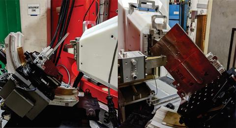
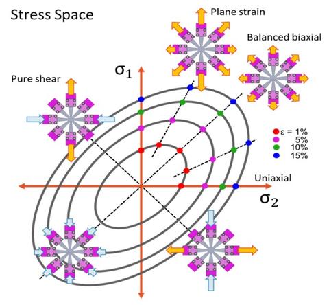
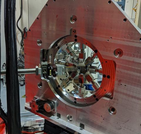
Octo-Strain
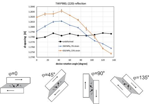
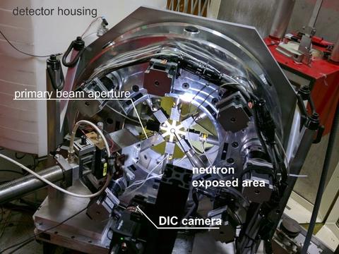
Octo-Strain is an 8-arm loading device for measuring the multi-axial yield function of industrial sheet metals. Each arm is independently controlled either through force (load cell) control, grip displacement control, or strain control. The latter is made possible by a digital image correlation (DIC) system which measures the strain tensor in the neutron gage area during straining. Octo-Strain has an effective rotation range of 180° about the scattering vector which allows the determination of the principal stress axes. The main advantage of the 8-arm design over cruciform machines (two pairs of opposing arms at 90°) is a significantly higher strain range comparable to that of deep drawing devices. Other advantages are path changes along 45° directions which cannot be achieved with cruciform devices.

A central circular recess is machined or masked by spotweld-sandwiching; this recess diameter limits the size of the neutron exposed area, and it is limited by the material strength and the maximum actuator force. Currently, the maximum actuator force is 15 kN but an upgraded Octo-Strain with 40 kN actuator force is nearing completion.
In order to avoid creep a measurement on Octo-Strain deforms the sample continuously but a low strain rate. DIC strain measurements are done for the starting angle in each rotation cycle. Neutron measurements are done at discrete rotation angles.
Due to buckling limits for compressive loads, Octo-Strain operates predominantly in strain space above the pure shear region where e2 > -e1.Stresses during the equi-biaxial deformation of an AISI-1010 mild steel, followed by a plane-strain deformation equivalent to bending. The inserted pictograms show displacement magnitudes. Stresses were determined from neutron diffraction measurements using Octo-Strain. Credit: T. Gnaupel-Herold
A recent upgrade in load capacity can achieve peak loads up to 40 kN in each arm, thus allowing multi-axial deformation tests of advanced high strength steels (AHSS).
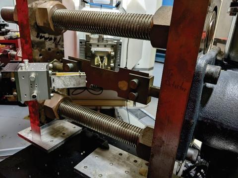
Shear device
With the exception of small strains, shear modes in sheet metal deformation are not accessible to Octo-Strain due to sample buckling under compressive load. Therefore, a device was developed that allows measurements above and below the region e2 = -e1 in strain space. The shear device features two independent actuators that allow a variety of straining modes from pure shear to mixed modes with added compression or tension. Uniaxial tests are also possible.
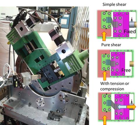
The rotation range of the shear device is 135° which is sufficient to allow the tracking of principal axis rotations. Typical shear areas are 10 mm ´ 40 mm, and the two actuators allow up to 40 kN load. Typical neutron illuminated areas are 6 mm squares.
Digital Image Correlation System (DIC)
Strains in multi-axial deformation are necessarily inhomogeneous due to changes in cross sectional area (Octo-Strain recess) or due to the proximity of edges and grips. Digital image correlation analyzes speckle patterns for changes in location of individual speckles which makes DIC an ideal tool for resolving the local tensor of plastic strains during straining in real time. It allows to identify regions of sufficient homogeneity and size suitable for neutron diffraction.
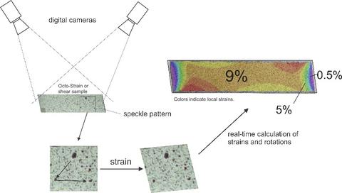
The DIC system allows output of the thus-obtained strain data in analog or digital form. The output can be read by the controller of both Octo-Strain and the shear device, thus enabling true strain control in multi-axial straining experiments. Multi-axial straining is typically performed continuously because of the immediate onset of load drop if straining is stopped (creep). As a consequence, strain is being accumulated during a neutron measurement. The DIC system and the neutron data collection are separate systems; matching of neutron data and strain data happens in the PF analysis software through time-stamping in which strain data collected during a neutron measurement are binned and averaged.
Contacts
-
(301) 975-5380