
Official websites use .gov
A .gov website belongs to an official government organization in the United States.
Secure .gov websites use HTTPS
A lock (
) or https:// means you’ve safely connected to the .gov website. Share sensitive information only on official, secure websites.
Time and Frequency from A to Z, C to Ce
A comparison between a device under test and an established standard, such as UTC(NIST). When the calibration is finished it should be possible to state the estimated time offset and/or frequency offset of the device under test with respect to the standard, as well as the measurement uncertainty.
The base frequency of a transmitted electromagnetic pulse or wave on which information can be imposed by varying the signal strength, varying the base frequency, varying the wave phase, or other means. This variation is called modulation. If the carrier frequency is derived from a source that is traceable to the International System (SI), the received signal can be used to calibrate other frequency sources.
The table lists the carrier frequencies of several radio transmissions commonly used as frequency standards. In metrology, an unmodulated signal from an oscillator (such as a 10 MHz sine wave) is also sometimes referred to as a carrier frequency.
| Radio Signal | Carrier Frequency |
|---|---|
|
WWVB |
60 kHz |
|
WWV |
2.5, 5, 10, 15, 20 MHz |
|
WWVH |
2.5, 5, 10, 15 MHz |
|
Global Positioning System (GPS) |
1575.42 MHz (L1) |
A type of calibration that uses the carrier frequency of a radio transmission as a measurement reference, rather than information modulated onto to the carrier, such as a time code or on-time marker. Carrier phase measurements have been made for many years using low frequency radio signals stations such as WWVB. However, the carrier phase measurements with the smallest uncertainties and highest resolution are made using satellite signals where the carrier frequencies are typically much higher.
Cesium oscillators can be primary frequency standards since the SI second is defined from the resonance frequency of the cesium atom (133Cs), which is 9,192,631,770 Hz. A properly working cesium oscillator should be close to its nominal frequency without adjustment, and there should be no change in frequency due to aging. However, environmental conditions (motion, vibration, magnetic fields, and so on) do cause small frequency shifts.
Commercially available oscillators use cesium beam technology. Inside a cesium oscillator, 133Cs atoms are heated to a gaseous state in an oven. Atoms from the gas leave the oven in a high-velocity beam that travels through a vacuum tube toward a pair of magnets. The magnets serve as a gate that allows only atoms of a particular magnetic energy state to pass through a gate into a microwave cavity, where they are exposed to a microwave frequency derived from a quartz oscillator. If the microwave frequency matches the resonance frequency of cesium, the cesium atoms change their magnetic energy state.
The atomic beam then passes through another magnetic gate near the end of the tube. Only those atoms that changed their energy state while passing through the microwave cavity are allowed to proceed to a detector at the end of the tube. Atoms that did not change state are deflected away from the detector. The detector produces a feedback signal that continually tunes the quartz oscillator in a way that maximizes the number of state changes so that the greatest number of atoms reaches the detector. Standard output frequencies are derived from the locked quartz oscillator as shown in the illustration.

The Q of a commercial cesium standard is a few parts in 108. The beam tube is typically less than 0.5 m in length, and the atoms travel at velocities of greater than 100 meters per second inside the tube. This limits the observation time to a few milliseconds, and the resonance width to a few hundred hertz. The stability at 1 second is typically 5 × 10-12, and can reach a few parts in 1014 after one day of averaging. The frequency offset is typically near 1 × 10-13 after a brief warm-up period.
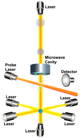
The current state-of-the-art in cesium oscillator technology, the cesium fountain oscillator is named after its fountain-like movement of cesium atoms. A cesium fountain named NIST-F2 serves as the primary standard of time interval and frequency for the United States.
A cesium fountain works by releasing a gas of cesium atoms into a vacuum chamber. As indicated in the illustration, six infrared laser beams are directed at right angles to each other at the center of the chamber. The lasers gently push the cesium atoms together into a ball. In the process of creating this ball, the lasers slow down the movement of the atoms and cool them to temperatures a few millionths of a degree above absolute zero. This reduces their thermal velocity to a few centimeters per second.
Vertical laser beams gently toss the ball upward and then all of the lasers are turned off. This little push is just enough to loft the ball about a meter high through a microwave-filled cavity. Under the influence of gravity, the ball then stops and falls back down through the microwave cavity. The round trip up and down through the microwave cavity lasts for about 1 second, and is limited only by the force of gravity pulling the atoms downward. During the trip, the atomic states of the atoms might or might not be altered as they interact with the microwave signal. When their trip is finished, another laser is pointed at the atoms. Those atoms whose states were altered by the microwave signal emit photons (a state known as fluorescence) that are counted by a detector. This process is repeated many times while the microwave signal in the cavity is tuned to different frequencies. Eventually, a microwave frequency is found that alters the states of most of the cesium atoms and maximizes their fluorescence. This frequency is the cesium resonance.
The Q of a cesium fountain is about 1010, or about 100 times higher than a traditional cesium beam. Although the resonance frequency is the same, the resonance width is much narrower (< 1 Hz), due to the longer observation times made possible by the combination of laser cooling and the fountain design. The combined frequency uncertainty of NIST-F2 is near 1 × 10-16.