
Official websites use .gov
A .gov website belongs to an official government organization in the United States.
Secure .gov websites use HTTPS
A lock (
) or https:// means you’ve safely connected to the .gov website. Share sensitive information only on official, secure websites.
3-Axis Accelerometer Calibration Based on Intrinsic Properties
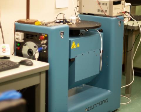
Two-axis position and rate table used for calibration of three axis accelerometers by intrinsic properties.
We have developed a calibration method for three axis accelerometers that is based on the rotation of the device under test in the earth’s gravitational field using a two-axis rotation and rate table. We reduce our measurement uncertainties by defining the accelerometer by its intrinsic properties, which have a mathematical relationship to the traditionally used cross axis sensitivity matrix in the frame of reference of the test equipment.
Cross axis sensitivity is defined by the relationship of the output of the accelerometer by an excitation that is perpendicular to its intended axis of sensitivity. For example, the sensitivity s of an x axis accelerometer to an excitation along the y axis would be represented by sxy. Using this definition, the cross axis sensitivity matrix can be written as:
$$S=\ \left[\begin{matrix}s_{xx}&s_{xy}&s_{xz}\\s_{yx}&s_{yy}&s_{yz}\\s_{zx}&s_{zy}&s_{zz}\\\end{matrix}\right]$$
where sxx, syy, and szz are the sensitivities of the x, y, and z accelerometers for excitations in the x, y, and z directions, respectively, and the other terms represent the cross-axis sensitivities. Note that this matrix definition for accelerometer response is dependent on the alignment of the accelerometer to the test instrument since x, y, and z represent the frame of reference to the test instrument.
What is new?
The cross-axis sensitivity of a well-designed accelerometer to first order can be attributed to a slight misalignment of the accelerometer to its intended axis. For a three-axis accelerometer this misalignment can result due to a number of reasons, but the end result is that three axes are not perfectly orthogonal to each other. This fact forms the basis of our intrinsic-property description of the device, defined by the magnitude of the sensitivity of each accelerometer and the angles between them. We designate unit vectors \(\hat{u}\), \(\hat{v}\), and \(\hat{w}\) to point in the directions of maximum sensitivity of the x, y, and z accelerometers, respectively. We designate the terms: U, V, and W to be the scalar sensitivities of the x, y, and z accelerometers in their direction of maximum sensitivity, and φuv, φvw, and φwu to be the angles between them. More information on the method can be found in the reference below [1].
Why is this method needed?
There has been tremendous growth over the last decade in the production and commercial application of three axis accelerometers, gyroscopes, and inertial measurement units, most of which communicate their measurements digitally. Yet the world’s National Measurement Institutes, who work together under the Metre Convention’s Mutual Recognition Arrangement to establish the degree of equivalence of measurements, only directly support single axis analog reference transducers. The degree of equivalence of measurements between countries is important since it is only to this level of uncertainty that a measurement by a National Measurement Institute in one country is equivalent to a measurement in another. For this reason, we strive to continuously advance our measurement capabilities and participate in international key comparisons on a periodic basis so that we can deliver the lowest possible uncertainties to our stakeholders.
[1] Gravity-Based Characterization of Three-Axis Accelerometers in Terms of Intrinsic Accelerometer Parameters, Volume 122, Article No. 32 (2017) https://doi.org/10.6028/jres.122.032
Contacts
-
(301) 975-2070