
Official websites use .gov
A .gov website belongs to an official government organization in the United States.
Secure .gov websites use HTTPS
A lock (
) or https:// means you’ve safely connected to the .gov website. Share sensitive information only on official, secure websites.
IROS 2019 Robotic Grasping and Manipulation Competition: Manufacturing Track
The goal of the competition is to test the capabilities of a robot system in performing assembly operations relative to a small-parts manufacturing process using assembly task boards. The task board for this competition was designed based on similar task boards that have been developed as part of a NIST project to support the advancement of robotic systems to support variable small-batch production runs in future manufacturing systems (see: https://www.nist.gov/el/intelligent-systems-division-73500/robotic-grasping-and-manipulation-assembly/assembly).
Competition parts have been selected to replicate typical manufacturing assembly operations. Competing robot systems should recognize, grasp, and assemble various parts including flexible ones, and assemble a new product by quickly reconfiguring the system. The limited competition time and bonus applied remaining time should encourage autonomous system designs where the use of perception (machine vision and force sensing) will eliminate the time associated with teaching (also called lead through programming) and the need for jigs (also called fixturing). The principles of design & manufacture make part data readily available to the automated systems in the form of Computer-Aided Design (CAD) data. Therefore, all CAD models will be made available to competitors.
The manufacturing track of the IROS 2019 Robotic Grasping and Manipulation Competition will consist of two subtasks; an assembly subtask and a disassembly subtask using an assembly task board. Below is the design for a practice assembly task board as shown in Figure 1. The parts used in the competition will be primarily the same parts found in this example task board along with a couple of surprise parts. An example kit layout is also provided to present parts for the assembly subtask. During the competition the location of the parts on the task board and the kit will change. The locations of the task board and kit placement will be defined by the judges and CAD files for the task board layout will not be presented to competitors until the start time of the competition. This is to highly encourage the use of machine vision and force sensing in system designs. Design your autonomous systems and practice accordingly.
- Preliminary rules and scoring for the competition (subject to change): Rules_V4.pdf
- Instructions for producing practice task board: Practice Task Board.pdf
- Laser Cut Board files (see instructions for direct link to order): Laser_Cut_Board.zip
- SOLIDWORKS Computer Aided Design (CAD) files: CAD_Files.zip
- Stereolithography (STL) files: STL_Files.zip
- Kit files: Kit_Layout.zip
- Standard for the Exchange of Product data (STEP AP 203) files: STEP_Files.zip
- Modified part designs: modified_parts.zip
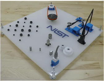
Figure 1. Practice Task Board
Note: The orientation of the cable routing quadrant of the practice board is different from the orientation shown in the figure.
Contacts
-
(301) 975-3455