
Official websites use .gov
A .gov website belongs to an official government organization in the United States.
Secure .gov websites use HTTPS
A lock (
) or https:// means you’ve safely connected to the .gov website. Share sensitive information only on official, secure websites.
Taking Measure
Just a Standard Blog
Item 0554 submitted for your bewilderment.
Much like your attic, garage or basement, the NIST archives are home to quite a number of arcane objects of unclear origin and purpose. We periodically collect these victims of misplaced paperwork and present them in a series we call "Unidentified Museum Objects." We invite you to put on your thinking caps and help us figure what these relics might be.
New Mysteries
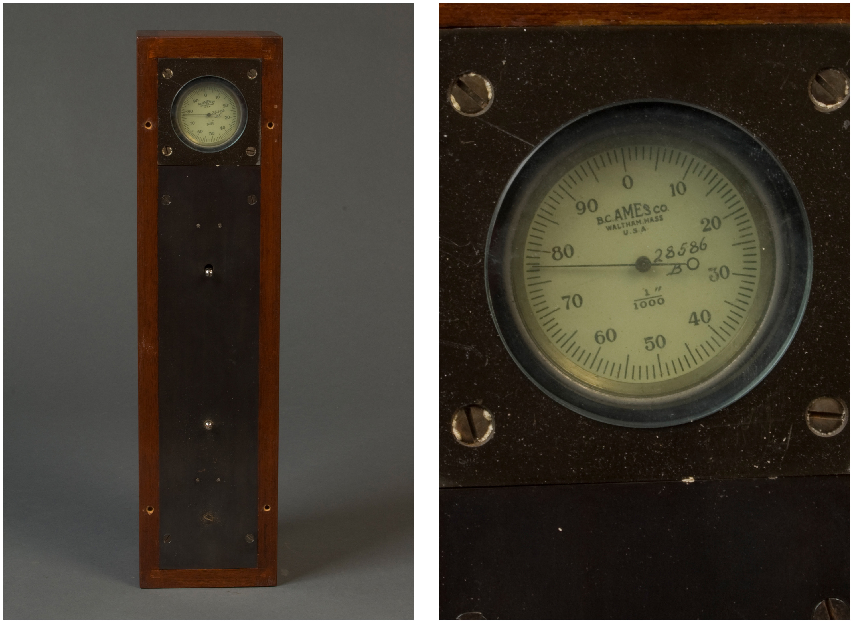
Item 0290: The museum collection notes this is possibly a strain gauge and certainly made by the B.C. Ames Company of Waltham, Massachusetts. Their tagline is “Masters of Measurement.”
The gauntlet has been thrown.
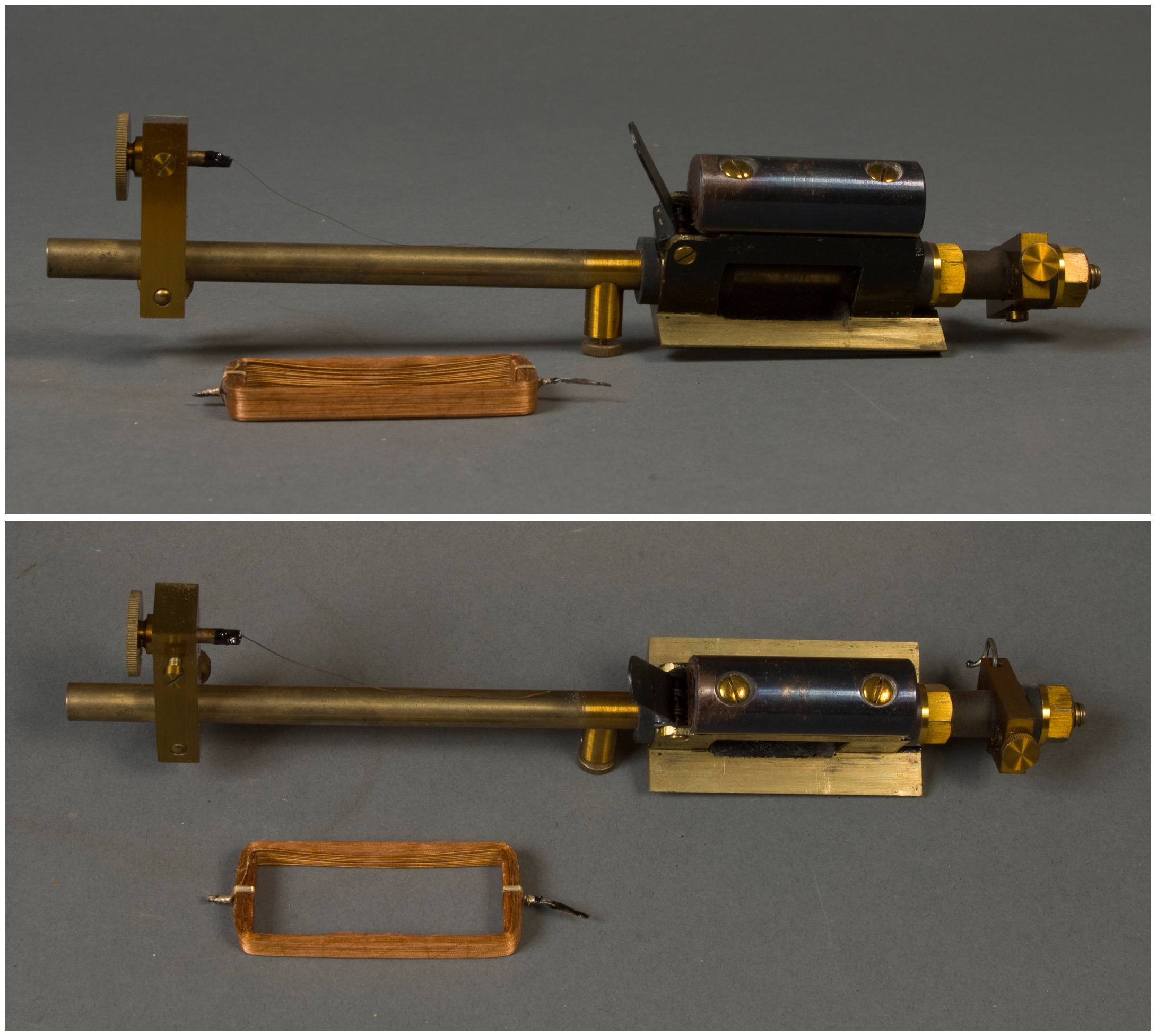
Item 0304: The museum collection simply describes this one as an “unidentified metal instrument with a wire coil.” Sounds about right.
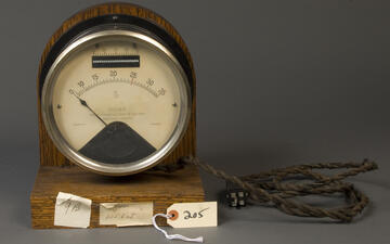
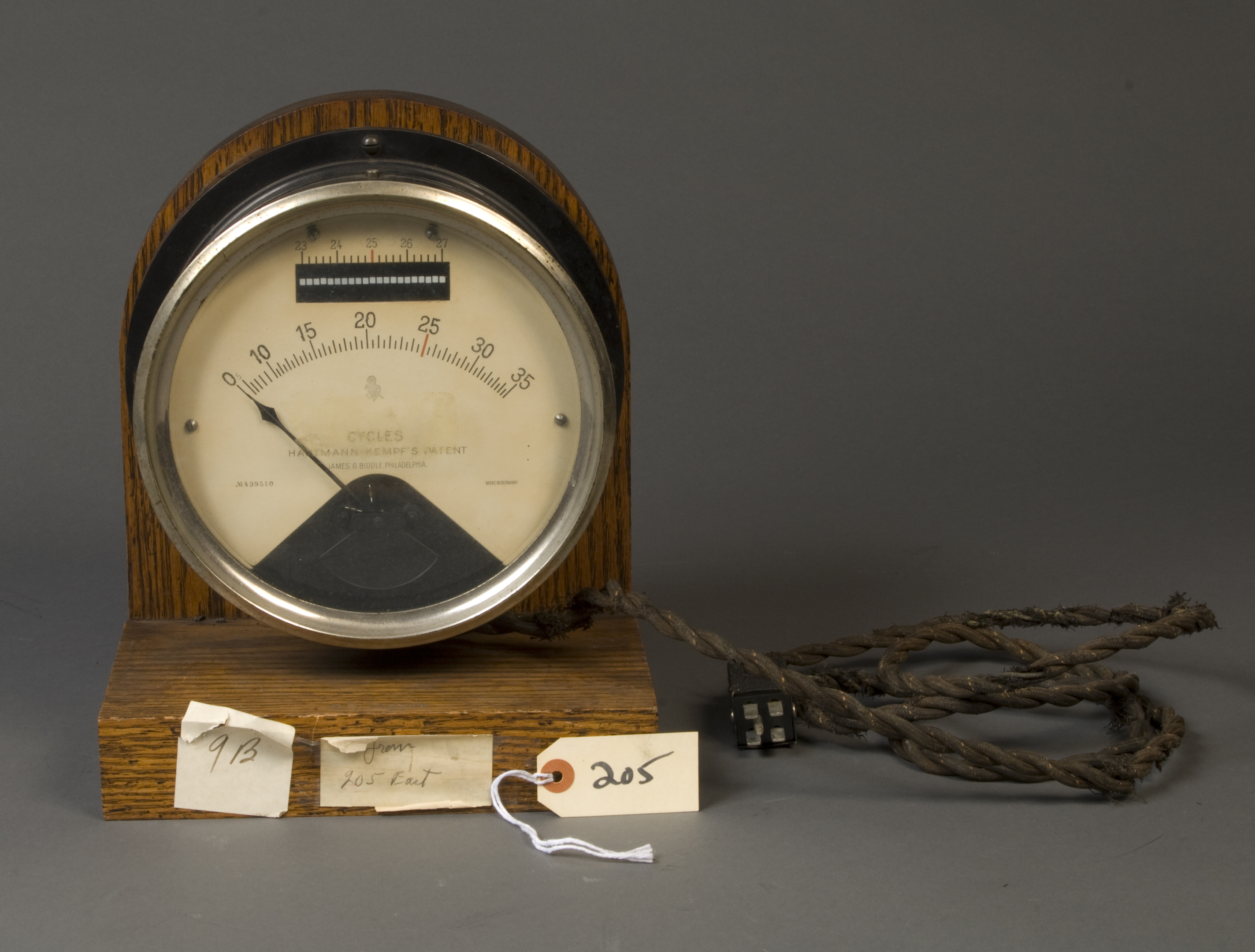
Item 0554: The face of the instrument reads “Hartmann-Kempf’s Patent,” which, when searched for, turns up a patent for a frequency-measuring instrument. Also on the face of the instrument is the name of James G. Biddle of Philadelphia. According to the Harvard Collection of Historical Scientific Instruments, the Biddle company was an importer of German instruments. Megger, which makes electric test equipment, has since bought Biddle.
If you’ve got any inkling of what one of these thingamabobs might be, let us know in the comments.
Mysteries Solved(?)
Not all mysteries are destined to remain unsolved. Here are a few objects from columns past whose uses have become slightly more clear thanks to the efforts of our intrepid researchers.
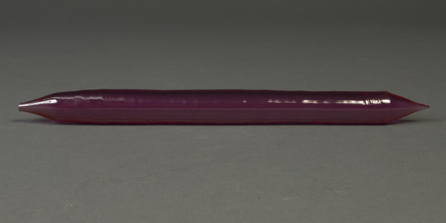
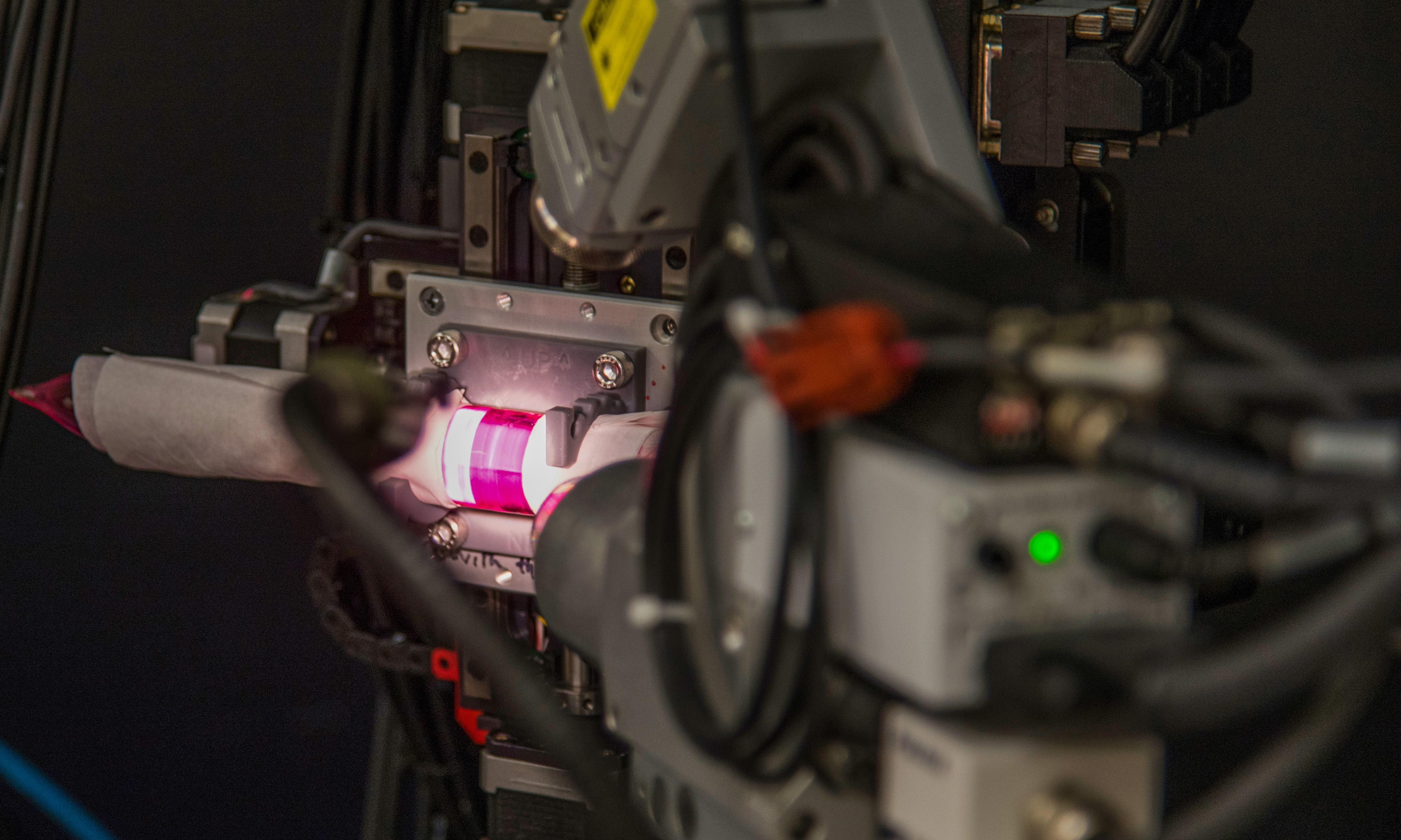
Item 0497: David LaVan, a mechanical engineer in NIST's Material Measurement Laboratory, took item 0497, a red glasslike shard that was featured in Unidentified Museum Objects, Vol. II, into his lab for testing. LaVan and Mark Vaudin used 2D X-ray diffraction to determine that the object is "very likely ruby." That is, the object's measurements were consistent with what you'd expect to find for a cylindrical single crystal of the gemstone ruby, LaVan said. He further notes: "Growing single crystals was an art and very important in the earlier days of many fields of optics and microelectronics. A single ruby crystal of that size and shape would likely have been used in a very early laser."
Testing item 0497 took several hours and involved overcoming several logistical challenges. A special part was custom 3D-printed to enable the object to be mounted in the X-ray diffraction instrument.
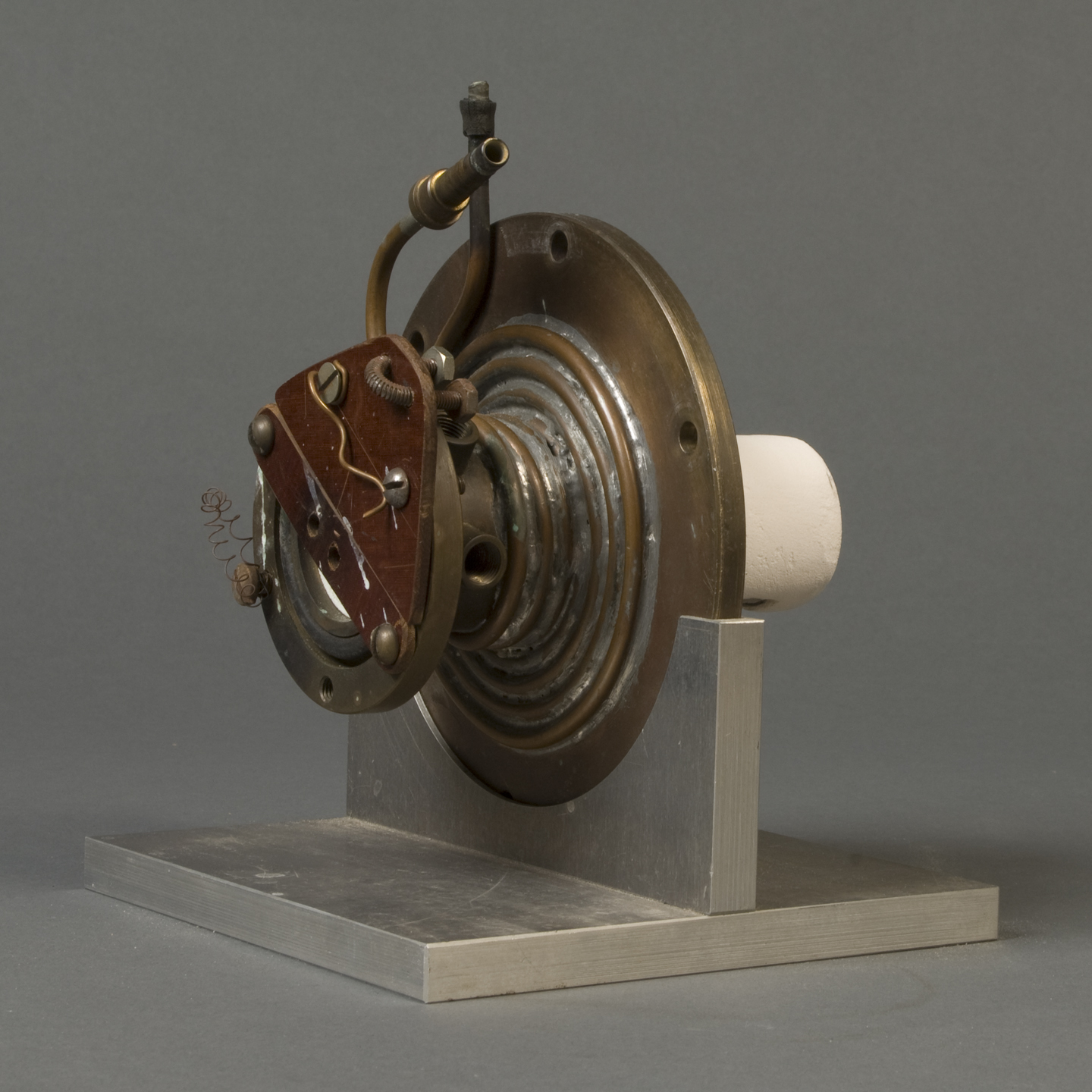
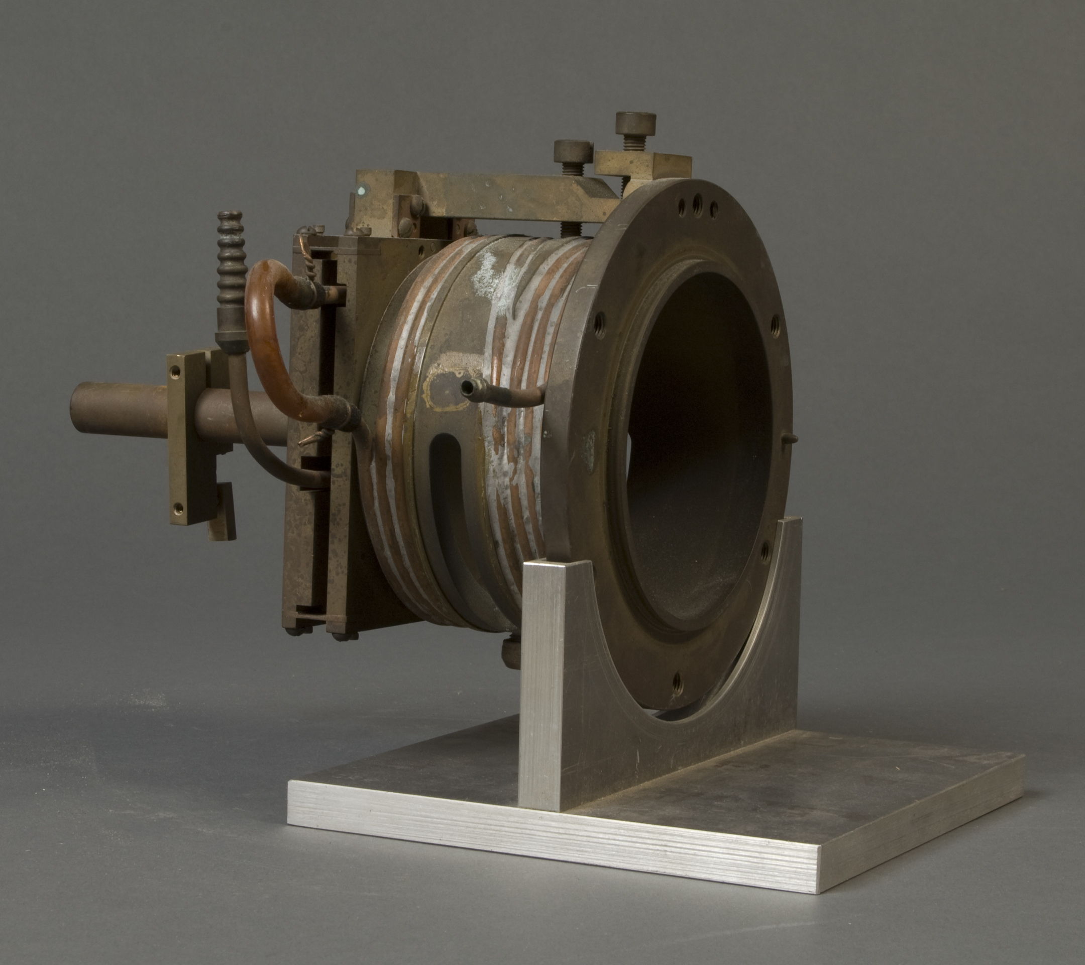
Items 0305 and 0306: John Sieber, a research chemist in the NIST Material Measurement Laboratory, writes that "Items 0305 and 0306 fit together. To me, it looks like an accessory for X-ray diffraction (XRD), where the sample sits on the white cylinder of 0305 and the two parts are assembled with the white cylinder inside 0306."
This concludes this installment of Unidentified Museum Objects. Again, if you have an idea as to what any of these things might be, let us know in the comments.
Until next time!
About the author

Related Posts


Comments
item # 0305 looks like a thermostat
Concerning the Planck Napkin, just goes to show that the smarter you think you are, the more you realise that
there is always more to learn..
0305 & 0306 look like an old water or LN2 cooled trap used in high and ultra high vacuum process systems or mass spectrometer.
Item 0554 - the Hartmann-Kempf meter - is definitely an electrical frequency meter. Note the dial scale only goes to 35 cycles. Also note 25 cycles has a red line and above the dial is some sort of indicator ranging from 23 to 27 cycles. Whatever the application, it appears to be made for the purpose of measuring frequency very close to 25 Hz. Pennsylvania Railroad (and others?) experimented with electric drive trains operating at 25 Hz in the early 1900's. They had a generator at the Safe Harbor Dam which generated AC power at 25 Hz for the railroad. Could be related to that.
The early traction systems, and the first Niagara power plant were 25Hz.
The NYC to Washington DC Amtrak line is still 25Hz!
(Thx to the magic of google and wikipedia)
I agree; the top part is a reed frequency meter, and the dial... well, seems redundant.
I don't see it as being useful today because 50 and 60Hz AC seem to run the world, and that's beyond the scale of this device.
Most of the power stations built in the last century have these, but the meters are relevant to the line frequency in use.
I think the idea with 2 was a wide-range meter so you could tell what the reading was if it was far off, and the smaller scale so you could get a precise reading.
As Mr. Proctor states, is definitely a frequency meter for 25 cycles per second measurements. The lower indicator is the rough measurement and the upper indicator is the fine measurement. The upper indicator works by resonant magnetic reeds which are very accurate though limited to a small frequency bandwidth due more to space requirements. The lower indicator is a movable vane type which varies in direction according to the frequency. Two movement coils, using inductance and resistance coils, placed at right angles use the same input source. At frequency of input, increased current in one coil causes deflection in one direction while decreased current in the other coil causes deflection in the opposite direction. The resultant field gives the frequency indication by vane position. It appears this was a switchboard meter that was saved as a souvenir and mounted. They were used, and some still are, at many places, such as generating stations, substations, and railroad equipment. As a test technician, I worked on the actual equipment at the Safe Harbor and Holtwood dams generating stations and some Pennsylvania Railroad substations and probably used an identical meter. Most transformers, motors, lighting, and other system loads and devices did not require accurate frequency to operate properly. Some system protective relays require accurate settings based on frequency. On 25 cps systems, as on 60 cps (Hertz), it is important to keep the frequency extremely close to the established system frequency because clocks on the system would run fast or slow depending on the frequency. Time corrections are made by raising or lowering the frequency on generators a very slight amount for some period of time. This meter was probably a station meter that may have been used to set the entire connected power grid to the desired frequency. The railroads, and many other entities, require very accurate time, though it doesn't always help them operate on time.
A number of the museum’s holdings have been photographed and are available to view at the NIST Digital Archives, www.nist.gov/digitalarchives. If you can contribute information about some of the objects there, email [email protected]
Item 0554 Might have been used on the 25 Hz AC power system used around
Toronto CA, maybe other places in the US around Niagara
RE: Item 0290
Hi <omitted>,
I recognize the face as being one of our older dial indicators, probably WWII or earlier, definitely pre-standardization. Other than that I can’t tell you much. It may have been something we built complete here or someone may have incorporated the dial indicator into there product. I might be able to tell you more if I was to examine it in person but the pictures don’t tell me anything more.
Regards,
Francis Gardner
B. C. Ames Inc.
1644 Concord Street
Framingham, MA 01701
I have a strong feeling that #0304 is a scale to weigh minerals. It was used during the gold rush when people were panning for gold and this would weigh the smallest amounts. the long bar would hold the rectangle tray that held the tray people would bring in.
#0306 appears to be a pipe threader of a threader of some kind. If you look at the top there is what appears to be a needle but really is a groove cutter. A pipe would fit on and the cutter would created the threads as the pipe revolved the spindle.
#554 is s an odd example of an AC line frequency meter, used to measure the accuracy of a generator's speed (or its governing unit's accuracy). The top thingie vibrates up and down, and the little white rods are of different lengths and each has a different resonant frequency. Why this one is set up for 25 Hz is beyond me...typically, these are for 50 Hz (Europe) or 60 Hz (US). Why these things are important is the inefficiency caused by off-frequency current: motors and other inductive loads are electrically tuned to match the line frequency. If the power is off, particularly if it is low, it will cause the motors or transformers to overheat. Plus, your mechanically-driven electric clocks will run slow.
I've never understood why they have the vibrating rods along with the meter, which is driven by a totally different system (I'm assuming it's some sort of RC network, but maybe not).
#0554 is some sort of dual scale frequency meter. The linear scale at the top is probably mechanically linked maybe by a coil or armature making it a "vibrating reed tachometer" much like the STICHT #9283. I would imagine the meter is the armature of a simple motor like the speedometer of a car. If the two agree... well, there ya have it, a twice accurate measurement.
My best guess,
DirtyJoeX
#205 looks like a gauge to sync up multi-phase power sources.
Item 0304. telegraph instrument
For those who don't kknow how an analog frequency meter works (#0554), here is an article on the Weston Analog Frequency Meter. The vibrating reed frequency meter was a built-in standard to compare to the analog meter's calibration.
https://www.electrical4u.com/weston-type-frequency-meter/
The Pennsylvania Railroad used 25 Hz for traction locomotives from 1915 onward. Amtrak was still using the 25 Hz system in 1976.
https://en.wikipedia.org/wiki/Amtrak%27s_25_Hz_traction_power_system
#304 - Looks like a device to wind wire to make a transformer.
Number 205 is a power line frequency meter.
Commenter Jack and others have already noted that object 0554 is a vibrating reed a.c. electrical frequency meter. Or rather it includes such a meter, probably as its most important part, giving visible output (upper scale) in a narrow range of frequencies than the (lower) analog meter. This narrow part of the frequency range, which was probably that of greatest measurement interest, was covered for a set of discrete ascending frequency-points by a series of the resonant tuned reeds. In this range the instrument would perhaps have been roughly as stable and well-calibrated at the closely-spaced frequency-points as a musical tuning-fork.
By contrast, the lower analog scale with moving needle was probably a separate auxiliary frequency meter clearly with wider range, but probably less-accurate calibration and poorer stability. This part was perhaps for auxiliary and run-up/guiding use e.g. as suggested below.
The instrument shown appears to be of a detailed design that would have fit it for use within the AC power generating industry, in connection with networks and generators providing nominally AC electrical power at '25 cycles'. (Note the red mark on both scales at the 25-cycle frequency point.) It is perhaps a little uncertain in view of the text of the patent to which a reference was provided whether this could have meant in practice a halved measure of frequency, equivalent to what would later be called 50 c/s. But early 25 c/s AC distribution systems did exist, e.g. Westinghouse's 19th-c. system at Niagara, though that seems to have been 2-phase. The flexible cord and plug attached to the much later meter shown, certainly post-1911 in date, has four wires, perhaps indicating its use with the 3-phase + neutral systems that took over from 2-phase generation.
The instrument shown looks clearly portable and may have been got up primarily for laboratory uses. But if it was also for use in the generating stations themselves, the uses may have included:
(a) to assist the frequency steering of a generator set that might wander out of whatever was the allowed tolerance band around the nominal supply frequency. In that use, the upper linear scale given by the vibrating-reed part of the instrument, of narrow range but good calibration and stability, would probably have been the main source of an accurate frequency-check.
(b) also to assist the run-up, and bringing into parallel connection, of additional generator sets at times of high community power demand. In that use, the tasks to be performed would have included starting up an extra generator, and aligning its output rather closely in frequency and phase with the already-running generator(s) before all could be connected in parallel together to supply the power demand jointly. The lower and less precise analog frequency meter could have been of use to monitor the run-up stage, then an operator could turn to the upper narrow-range scale to get a more precise and stably-calibrated frequency comparison using also another similar instrument connected to the already-running generator set.
(A separate instrument/a.c.-voltmeter would have been needed to monitor the (generally not constant) a.c. volt difference between 'live' lines or corresponding phases of the generators -- arising from the phase offset for the time being between their outputs.)
I don't know any details of operating procedure! But it seems possible that it included steering the frequencies of the generators that were to be paralleled, to be at a certain time-point nearly but not quite identical in frequency. An operator might then watch the voltmeter mentioned above for the slow phase-approach between the generators, perhaps judging this by the accompanying trend towards a minimum in the a.c. volts between their corresponding phases. Then (with any other criteria and procedural steps for the connection also satisfied) the operator might choose an appropriate moment, at or sufficiently close to coincidence of phase and frequency, to switch the generators in parallel so that they would jointly support the power demand. (Once paralleled, there would be a tendency, perhaps assisted, for the generators to lock in phase.)
Wild guess on #0554. It might by an boat speedometer ranging in 0-35 knots per hour.
Items 305 and 306 look strangely like parts of an ancient prototype of the similar compact, extremely low power cryocooler featured in Cryogenics, Major Accomplishments.
re 0554. Obviously the top is a vibrating reed frequency meter. How that is converted to the reading on the movement at the bottom is a good question.