
Official websites use .gov
A .gov website belongs to an official government organization in the United States.
Secure .gov websites use HTTPS
A lock (
) or https:// means you’ve safely connected to the .gov website. Share sensitive information only on official, secure websites.
CHAL-AMB2018-01-PD
Results for CHAL-AMB2018-01-PD: Part Deflection
1. Overview
The following plot and associated links summarize the data to be used for CHAL-AMB2018-01-PD: Part deflection, measured post-process on parts manufactured on the commercial build machine (CBM). The following sections provide brief descriptions of the measurement procedure and results. A more detailed measurement description, pictures of the parts, measurement reports, and analysis of results can be downloaded here (download link will be provided soon). It should be noted that the actual measurement procedure deviated slightly from the initial proposal:
- The tops of each ridge are ground, not machined.
- Three measurements are performed across each ridge, not two.
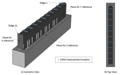
2. Measurement Procedure
Before any measurements are made, the tops of the 11 ridges are ground to provide smooth surfaces that can be accurately measured with a coordinate measuring machine (CMM). The height of the ground surfaces of each ridge relative to the top surface of the baseplate is calculated from 3 measurements made across the ridge and 2 measurements made on the baseplate, on either side of the part. Figure 1 illustrates the locations of the 55 CMM measurements. The 12 legs are then separated from the baseplate via electrical discharge machining (EDM), allowing the part to deflect upward due to the residual stress. The CMM measurements are performed a second time to measure the new relative height between the ridges and baseplate. Part deflection is calculated by the difference between these two sets of measurements.
3. Results
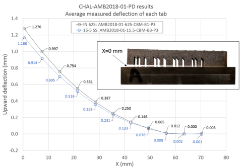
Results for the IN 625 bridge part (AMB2018-01-625-CBM-B1-P3) and the 15-5 bridge part (AMB2018-01-15.5-CBM-B3-P3) are presented in Figure 2. The points on the plot are the averages of the deflection calculated from the 3 measurement points across each ridge. The IN625 part experiences a greater amount of deflection (1.276 mm at ridge 1) compared to the 15-5 part (1.168 mm at ridge 1). The CMM measurement reports, CMM calibration certificate, pictures, and an Excel spreadsheet with the measurements and analysis is available here.
Contacts
-
(301) 975-6032
-
(301) 975-2265