
Official websites use .gov
A .gov website belongs to an official government organization in the United States.
Secure .gov websites use HTTPS
A lock (
) or https:// means you’ve safely connected to the .gov website. Share sensitive information only on official, secure websites.
Temperature Profiles during CAS Thermal Tests
REVISION DATE: 19-Feb-2019 13:39:22
CAS Thermal Testing
Two log files -- one from the Chamber (no data when it is not running) and other from MOBY FIBER SPLITTER program using 9V battery as dummy PD input.
UV CAS, MOBY CAS, VIS/NIR (NIST Stars aka SIRCUS) CAS, and Air-Luci CAS with OL455-12 at 10um and 5.503 A.
Three CAS are bare fiber Air-Luci is cosine collector; aiming at sphere is not aligned, pointing into sphere from about 15 cm.
The RSL SEI4500 is bare fiber also pointing into the sphere; it is outside the chamber as a monitor/control.
The RSL Fluke temp/humid sensor has channel 1 in the lab on the computer side and channel 2 about 7 cm from top of upper CAS in back.
CASs are double stacked and we started with most of the fiber bundles outside (UV CAS is long fiber, others not so much).
Wavelength calibrations are with Hg(Ne) and later, Ne emission lamps.
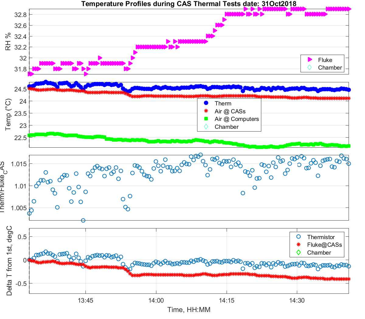
CONFIG 1: 31-Oct Chamber Door Open, test of Source Stability.
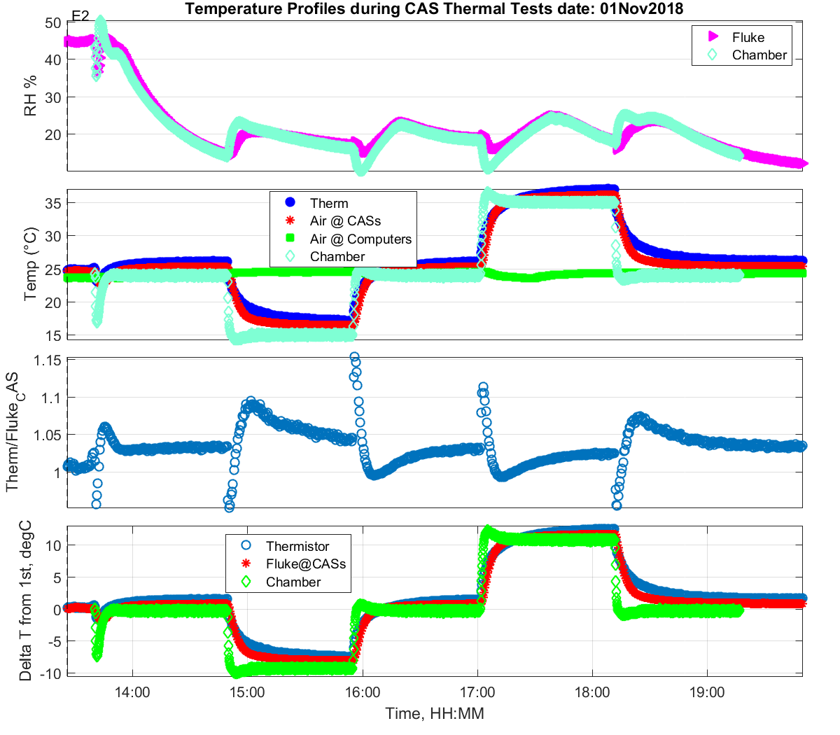
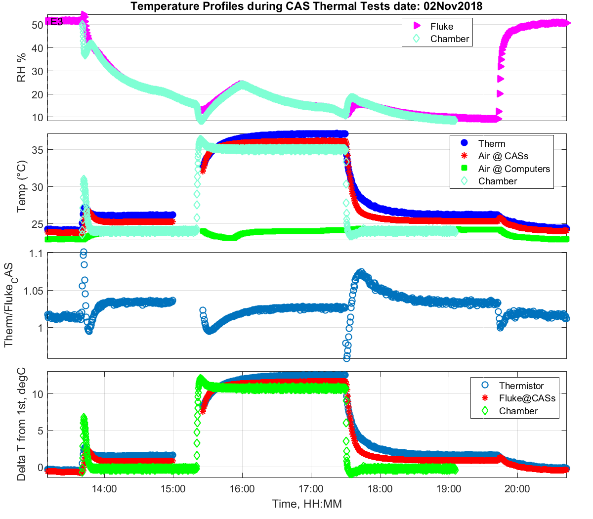
CONFIG 2: 01 & 02-Nov-2018 Runs with Thermistor in Fan airflow of Vis-NIR CAS 02014205; program not updating CCD temp during continuous scans.
CONFIG 3: 06, 07, 09-Nov-2018 Moved thermistor to PLG ring of Vis-NIR CAS, added fan cooling of Hg(Ne) to promote Ne lines, fixed program to update CCD temp.
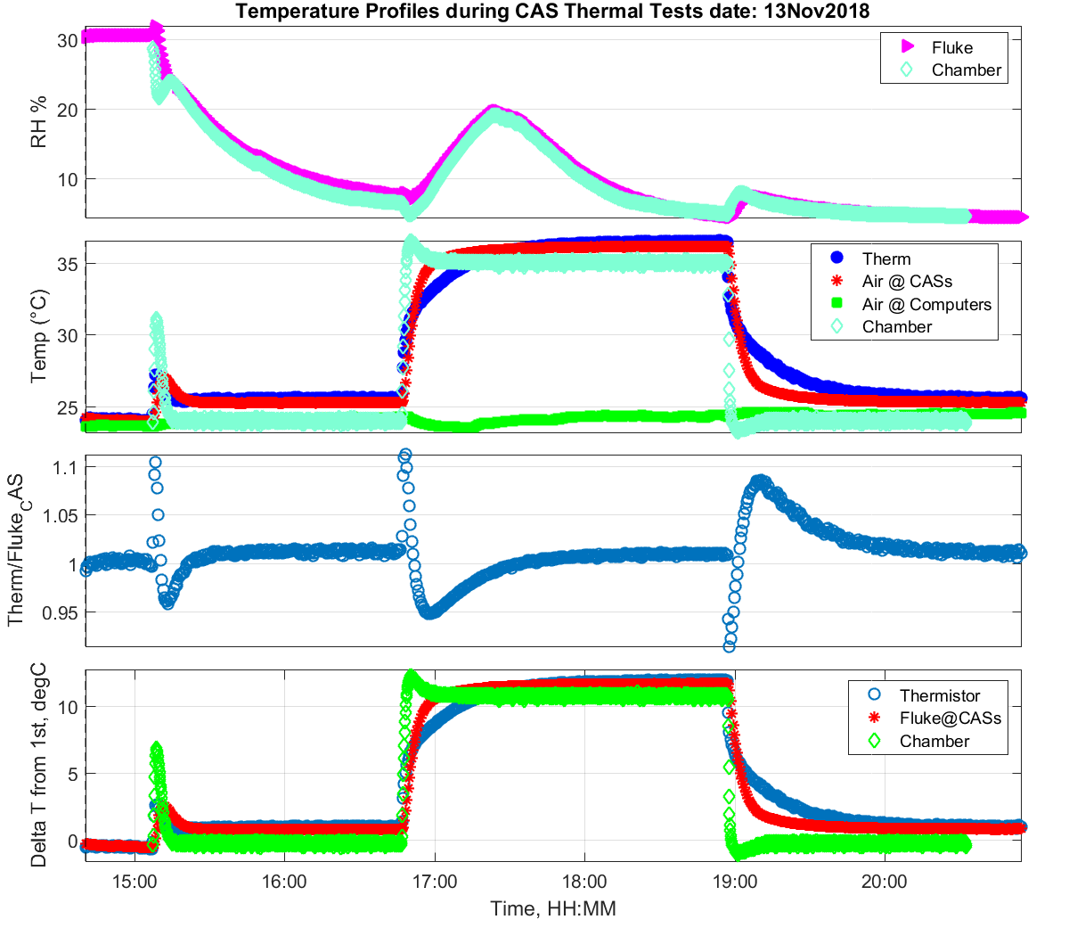
CONFIG 4: 13-Nov-2018 Moved UV and Vis-NIR CAS towards computers about 15cm, pulled as much fiber for all CASs as possible into chamber, added Ne to get some red lines. This evidently shifted the MOBY CAS head.
CONFIG 5: 14-Nov-2018 Found instability in MOBY CAS head alignment, must have moved when pulled fiber in; realigned for max signal & pushed MOBY CAS fiber back outside to get rid of bends.
The RH was always allowed to drift (otherwise takes too long to stabilize).
The CASs were left on, with the chamber door open when not running so would not overheat. SEI was off/on see logbook.
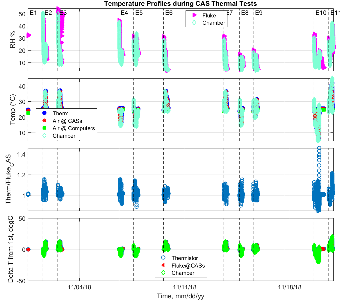
* E1 = Day 1: CONFIG 01: 31-Oct-2018 ambient, chamber off door held open at 90 deg; test of OL455-12 Stability; power glitch set filters to "none" and CASs saturated for part of run.
* E2 = Day 2: CONFIG 02: 01-Nov-2018 24/15/24/35/24 degC at 60 min soak interval
* E3 = Day 3: CONFIG 02: 02-Nov-2018 24/35/24 degC at 90/120/90 min soak intervals.
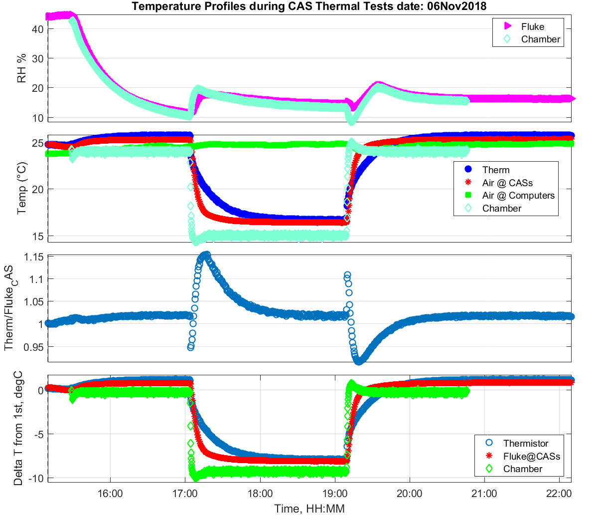
* E4 = Day 4: CONFIG 03: 06-Nov-2018 24/15/24 degC at 90/120/90 min intervals.
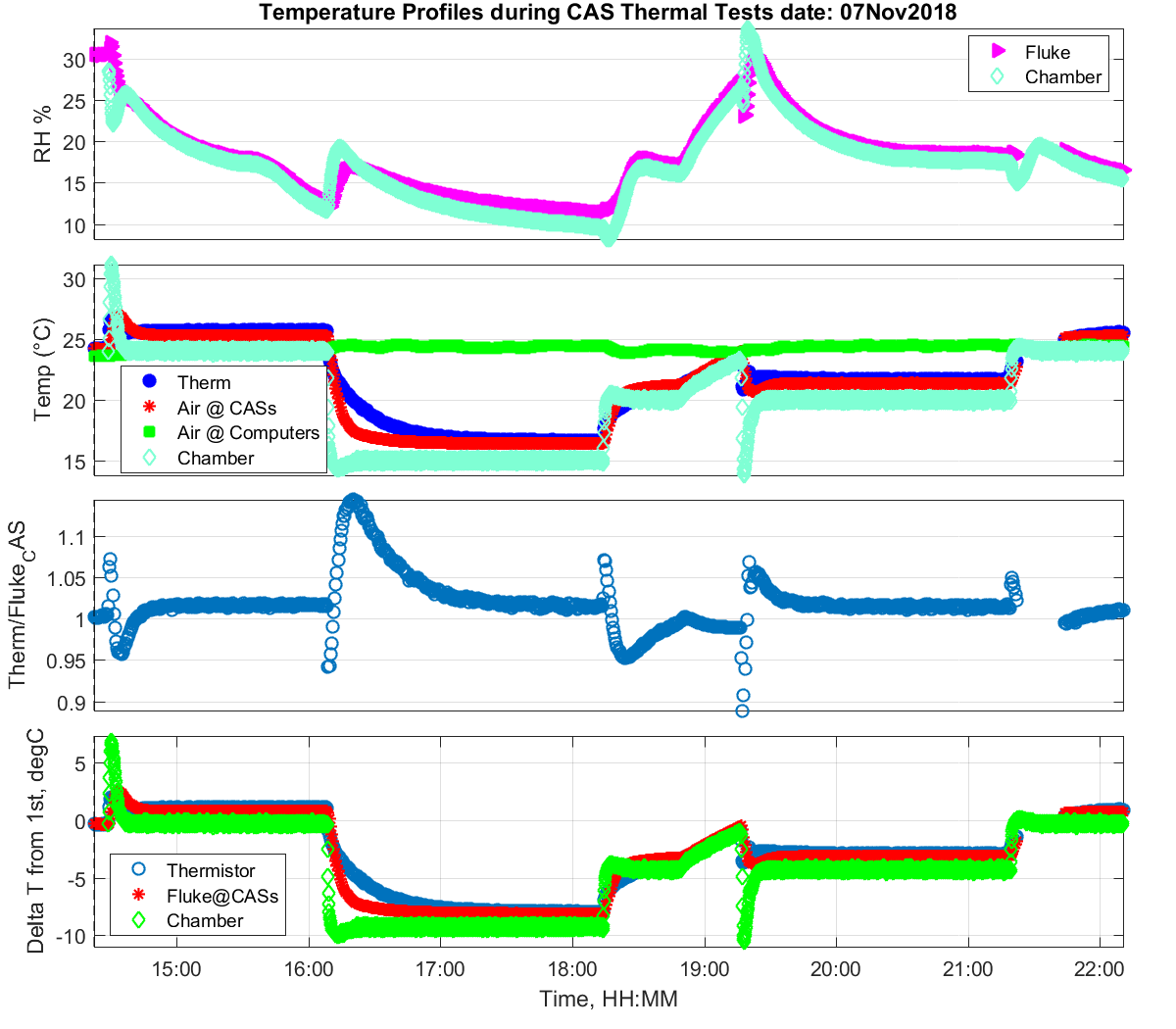
* E5 = Day 5: CONFIG 03: 07-Nov-2018 24/15/20/24 degC, 90/120/120/90 min intervals. Chamber PID failed to control during 20deg C for the entire step.
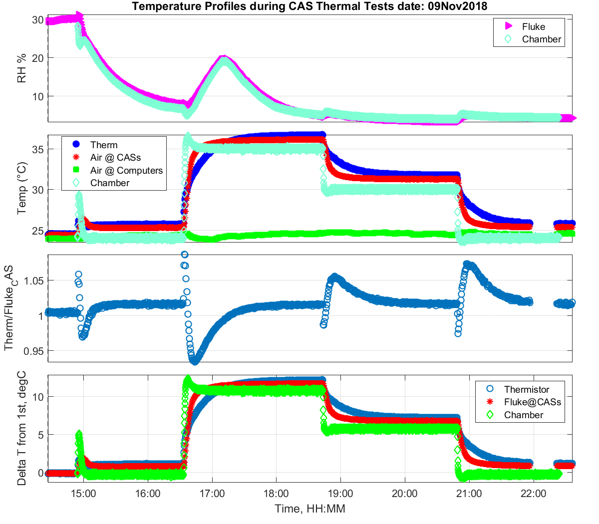
* E6 = Day 6: CONFIG 03: 09-Nov-2018 24/35/30/24 degC, 90/120/120/90 min intervals. Lost some Fluke logging when program stopped too early.
* E7 = Day 7: CONFIG 04; 13-Nov-2018 24/35/24 degC 90/120/90 min intervals Moved fibers so more length was inside, MOBY CAS saw big change.
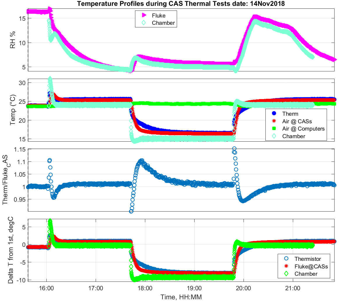
* E8 = Day 8: CONFIG 05: 14-Nov-2018 24/15/24 at 90/120/90; Pushed MOBY CAS fiber more outside, realigned head for max signal.
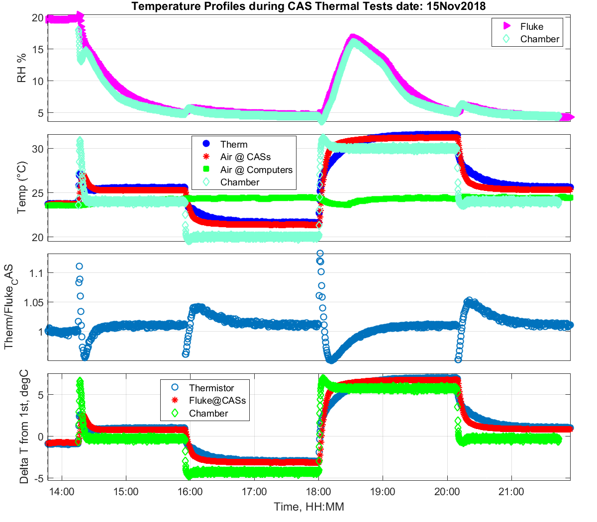
* E9 = Day 9: CONFIG 05: 15-Nov-2018 24/20/30/24 degC at 90/120/120/90
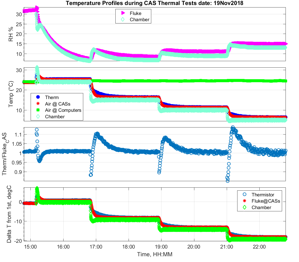
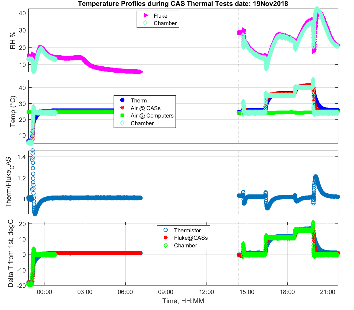
* E10 = Day 10: CONFIG 06: 19-Nov-2018 24/15/10/5/24 at 90/120/120/120/90 The MOBY and UV CAS were NOT in the chamber; Air Luci & NIST Stars were.
* E11 = Day 11: CONFIG 06: 20-Nov-2018 24/35/40/45/24 at 90/120/120/120/90 The MOBY and UV CAS were NOT in the chamber; Air Luci & NIST Stars were.
Contacts
-
(301) 975-2322