
Official websites use .gov
A .gov website belongs to an official government organization in the United States.
Secure .gov websites use HTTPS
A lock (
) or https:// means you’ve safely connected to the .gov website. Share sensitive information only on official, secure websites.
Realization of related photometric units
Realization of luminance (candela per square meter)
Luminance units are commonly established using a white reflectance standard or a transmitting diffuser illuminated by a luminous intensity standard lamp. The determination of the luminance factor of the material includes comparison of the incident and outgoing illuminances, which differ by three to four orders of magnitude, making precise calibration difficult. The uncertainty is also limited by that of the standard lamp used.
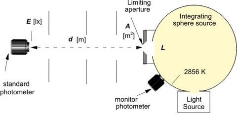
Another method is using the NIST standard photometers to realize the luminance unit on a reference integrating-sphere source operated at 2856 K. The sphere source is 15 cm in diameter and has a V(λ)-corrected monitor detector on the sphere wall. The source has a double sphere structure, the large sphere being irradiated by an intermediate 5 cm sphere which is irradiated by a quartz halogen lamp. The sphere source is operated by a constant-current power supply. A precision aperture 6 mm in diameter is attached to the exit port of the sphere source. The sphere source and the photometers are placed on the NIST photometry bench in a light tight box to reduce stray light. The sphere is aligned using the alignment laser and the side telescope. The side telescope sets the distance by aligning the aperture front surface with the origin of the bench. The illuminance 2.45 m from the sphere source is measured by the NIST standard photometers. The average luminance L (cd/m2) over the aperture plane is determined from the illuminance E (lx), the distance d (m), and the aperture area A (m2), as given by
$$L = E\: \frac{d^2}{A}$$
The luminance meter under test is calibrated by measuring the calibrated sphere source. This procedure is completed each time a luminance or luminance responsivity calibration is to be performed.
Realization of correlated color temperature (Kelvin)
The NIST color temperature scale is derived from the NIST spectral irradiance scale. Spectral responsivity measurements are used to calibrate the response of a filter radiometer, in turn used to estimate the temperature of a black-body radiator and hence provide the reference standard for spectral irradiance measurements. These reference standards, both for detectors and sources, are transferred to working standards for external calibrations, and used internally in deriving reference standards for colorimetric measurements. Three 1000 W FEL type quartz halogen lamps are maintained as the NIST color temperature primary standard lamps in the range of 2000 K to 3200 K. The spectral irradiance of these lamps is calibrated periodically against the NIST spectral irradiance scale at correlated color temperatures of 2000 K, 2300 K, 2600 K, 2856 K, and 3200 K.
To transfer the scale a PTFE plaque is placed in the photometry bench. The plaque is placed approximately 1 m from the lamp, and irradiated at normal incidence. The diffuse reflection at 45° is directed to a spectroradiometer. The plaque is mounted on a kinematic base, and can be removed when the luminous intensity is measured. The spectroradiometer is calibrated on a daily basis by the standard lamps. The lamp under test is mounted and the appropriate operating current is determined to produce the desired correlated color temperature.
Realization of flashing light scale (lx·s)
Flashing lights are widely used in many signaling applications in aviation, marine, and land transportation. To meet the industry needs, NIST established a facility for flashing light calibration under support by Federal Aviation Administration (FAA) in 1997 and maintains the unit of luminous exposure (lux-second) and provides a calibration service for flash photometers including aircraft anti-collision light meters.
Two different approaches were taken to calibrate flashing-light standard photometers: 1) based on electrical calibration of the current integrator (Electrical method), 2) based on electronic pulsing of a steady-state photometric standard (Pulsed photometry method). The principles of these two methods are illustrated in figure below.
Two methods used in the NIST realization of luminous exposure unit
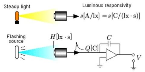
(a) Electrical method
Output charge:
Q[C] = C · V
Luminous exposure:
H [lx·s] = Q/s
Photometer responsivity:
sH [V/(lx·s)] = s/C
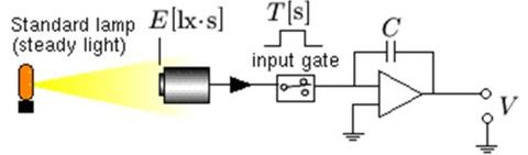
(b) Pulsed photometry method
Luminous exposure:
H [lx·s] = E · T
Photometer responsivity:
sH [V/(lx·s)] = V/(E · T)
Contacts
-
(301) 975-2332