
Official websites use .gov
A .gov website belongs to an official government organization in the United States.
Secure .gov websites use HTTPS
A lock (
) or https:// means you’ve safely connected to the .gov website. Share sensitive information only on official, secure websites.
Diagram of the two-capillary viscometer
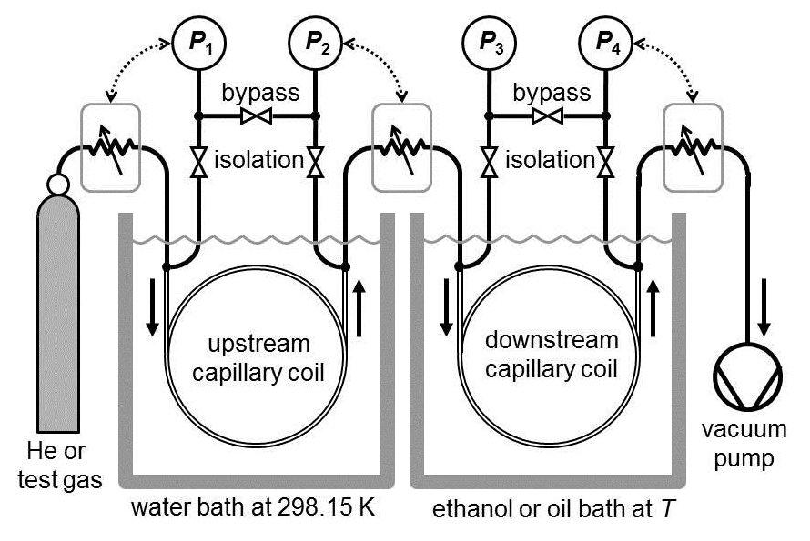
Schematic diagram of the two-capillary viscometer used by May et al. The coiled capillaries were made of nickel and had lengths of 7 m and an inside diameters of 0.8 mm. The arrows indicate the flow direction. The pressure gauges (P1, P2 and P4) controlled piezoelectric gas leak valves that are indicated by variable impedances. The isolation and bypass valves were used to eliminate the effects of the zero drift of the pressure gauges.