Official websites use .gov
A .gov website belongs to an official government organization in the United States.

Secure .gov websites use HTTPS
A lock (
) or https:// means you’ve safely connected to the .gov website. Share sensitive information only on official, secure websites.


Spectral comparator facilities
Ultraviolet spectral comparator facility (UV SCF)
The UV SCF is capable of measurements from 200 nm to 1800 nm, but it is optimized for the measurement of uniformity and spectral power responsivity of photodetectors and radiometers in the 200 nm to 500 nm spectral region—a range particularly important for calibrating and characterizing devices intended for germicidal UV applications, semiconductor manufacturing, and nondestructive testing of materials.The NIST Spectral Comparator Facilities (SCF) are built and designed for calibrating the spectral power responsivity of optical photodiodes and radiometers from 200 nm to 1800 nm. There are two facilities: one for measurements from 300 nm to 1800 nm called the Visible Near-Infrared Spectral Comparator Facility (Vis/NIR SCF) and one for measurements from 200 nm to 1800 nm called the Ultraviolet Spectral Comparator Facility (UVSCF). These facilities can measure the spectral power responsivity, spatial spectral power uniformity, irradiance, and effective area of photodiodes and radiometers.
Visible to near-infrared spectral comparator facility (Vis/NIR SCF)
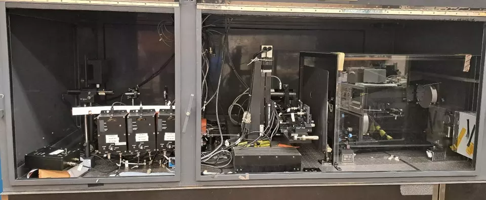
The Vis/NIR SCF measures and calibrates the spectral power responsivity of photodiodes and radiometers in the spectral region from 300 nm to 1800 nm. The setup uses a monochromator to select a wavelength from one of several light sources. The main source is a 100 W quartz-halogen lamp, which is focused onto the monochromator entrance slit. The beam exiting the monochromator is then focused onto the surface of the detector being measured.
The Vis/NIR SCF uses automated translation stages to position detectors into the optical beam for measurement. Detectors are mounted and aligned using 5 degrees of freedom: 3 linear translations and 2 rotational tilts. Silicon photodiodes serve as standards for calibrations over wavelengths from 300 nm to 1100 nm, and indium gallium arsenide (InGaAs) photodiodes are the standards from 700 nm to 1800 nm.
Detector calibrations are based on 2 principles: the substitution method and the two-beam method. The substitution method offers a way to calibrate a detector without current controlling the source’s output power that reaches the detector at each wavelength. In the method, the detector being tested is placed into the beam, and the electrical signal is recorded as the light is scanned over the desired wavelength range. Afterward, a NIST standard with a known absolute spectral power responsivity is substituted into the beam path, and the same measurement is repeated. Those results can then be compared, and using the standard’s absolute responsivity, the measurements can be translated into a calibrated responsivity for the test detector.
The two-beam method offers a way to account for fluctuations in the power of the lamp over time. In this method, a beamsplitter is added to the beam path just in front of the test detector creating a second beam that is directed to a monitor detector. In the two beam method both the detector and monitor detector measure the optical beam at the same time. Because the measurements are taken simultaneously, the ratio of the test detector signal to monitor signal yields a correction factor for any drifting of the source, and likewise for the ratio of the standard detector signal to monitor signal. This strategy reduces the noise and uncertainties in the measurements.
Shown below is the measurement equation that results from using both the substitution method and the two-beam method. Based on the substitution method, the test detector’s absolute spectral power responsivity SDUT is found from the known absolute spectral power responsivity of the standard SWS by multpliplying it by the ratio of the detector’s measured response RDUT to that of the standard in the same conditions Rs. With the application of the two-beam method, the test detector’s measured response is replace by a ratio of its measured voltage Vx to the simultaneously measured voltage of the montior detector Vmx multiplied by the detector’s preamplier gain GDUT. Likewise, the standard’s measured response is replaced with the ratio of its voltage Vs to the simultaneously measured voltage of the montior detector Vms multiplied by its preamplier gain GWS.
$$S_{\mathrm{DUT}} = \frac{R_{\mathrm{DUT}}}{R_{\mathrm{WS}}} \cdot \frac{G_{\mathrm{WS}}}{G_{\mathrm{DUT}}} \cdot S_{\mathrm{WS}} = \frac{V_{\mathrm{DUT}} / V_{\mathrm{DUT}}^{\mathrm{Mon}}}{V_{\mathrm{WS}} / V_{\mathrm{WS}}^{\mathrm{Mon}}} \cdot \frac{G_{\mathrm{WS}}}{G_{\mathrm{DUT}}} \cdot S_{\mathrm{WS}}$$
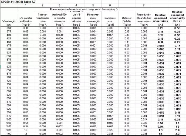
The use of the two-beam method and the substitution method has significantly reduced the calibration transfer uncertainties of the Vis/NIR SCF down to 0.005% in the visible spectrum. Example uncertainties are shown below.
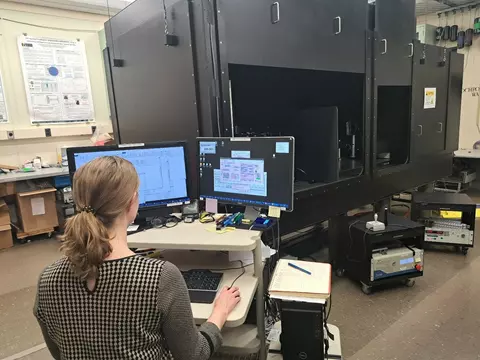
Ultraviolet spectral comparator facility (UV SCF)
The UV SCF is capable of measurements from 200 nm to 1800 nm, but it is optimized for the measurement of uniformity and spectral power responsivity of photodetectors and radiometers in the 200 nm to 500 nm spectral region—a range particularly important for calibrating and characterizing devices intended for germicidal UV applications, semiconductor manufacturing, and nondestructive testing of materials.
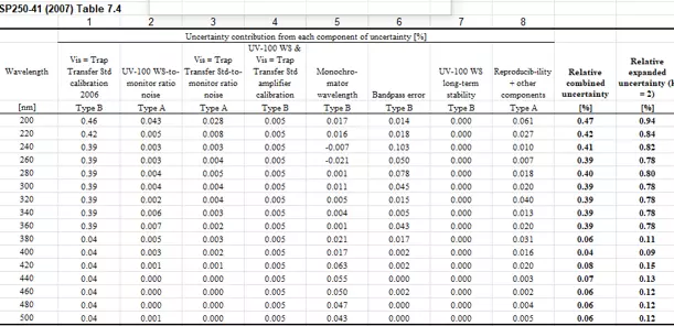
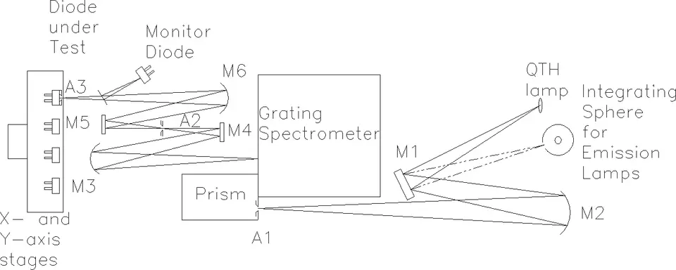
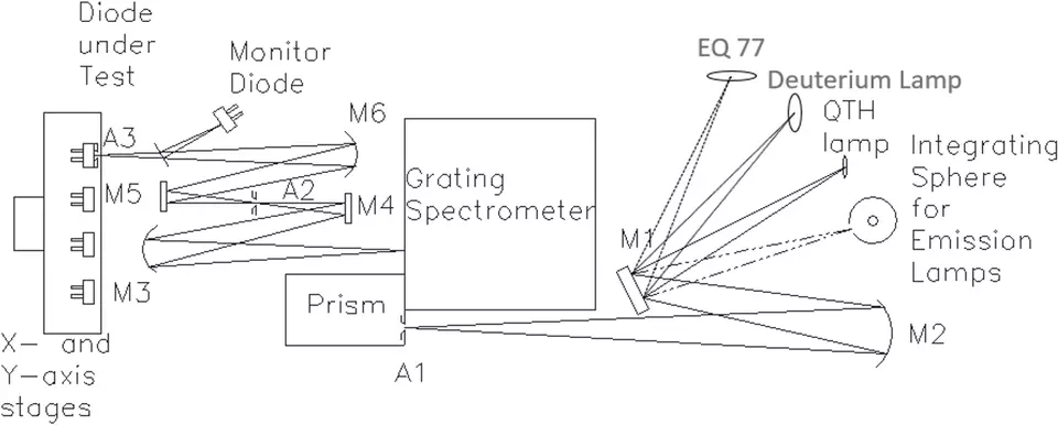
The UV SCF is similar in configuration and operation to the Vis/NIR SCF, but the optics in the system are designed to maximize the UV signal throughput. UV-enhanced silicon photodiodes serve as the transfer standards for the UV SCF. Two of the facility’s UV-rich light sources are a Deuterium lamp and a laser-driven light source (LDLS), which provides more power in the germicidal UV spectral region than a lamp. A diagram of the UV SCF is shown above and an example of the uncertainties below.
The UV SCF is similar in configuration and operation to the Vis/NIR SCF, but the optics in the system are designed to maximize the UV signal throughput. UV-enhanced silicon photodiodes serve as the transfer standards for the UV SCF. Two of the facility’s UV-rich light sources are a Deuterium lamp and a laser-driven light source (LDLS), which provides more power in the germicidal UV spectral region than a lamp. A diagram of the UV SCF is shown above and an example of the uncertainties below.