
Official websites use .gov
A .gov website belongs to an official government organization in the United States.
Secure .gov websites use HTTPS
A lock (
) or https:// means you’ve safely connected to the .gov website. Share sensitive information only on official, secure websites.
Peg-in-Hole Data
Data and Results from Three Peg-in-Hole Experiments for Improving Insertion Tasks
Introduction: A method was developed to reduce the point-based registration error by restoring the rigid body condition (RRBC method). Registration is the process of transforming one coordinate frame to another coordinate frame. The coordinate frame from which points are transformed is called the working frame and the coordinate frame to which points are transformed is called the destination frame. The RRBC method can be used to reduce the uncertainty of a hole location and thus, improve the success rate for insertion tasks. Peg-in-hole experiments were conducted to quantify the level of improvement.
Data and results from three peg-in-hole experiments may be down loaded from this site. A summary of the experiments is given below. Detailed description and information about these experiments and results may be found in [1] and [2].
How the RRBC method works: A grid of points is measured in two different coordinate frames – working and destination. The basic premise of the RRBC method is that the distance between any two points should be same in the working and destination frames – a fundamental concept for rigid bodies. However, due to systematic and/or random measurement error, the distances are not exactly the same in the two frames. Using the two sets of measured points (fiducials), the RRBC method calculates the corrections to the fiducials in the working frame so that the rigid body condition is restored. For points that are measured only in the working frame (targets), corrections for these points are linearly interpolated from the closest corrected fiducials. A detailed description of the RRBC method can be found in [3].
Experiments: To evaluate the effectiveness of the RRBC method as compared to the conventional registration method, three peg-in-hole experiments were conducted as they represent insertion tasks which are common in assembly operations.
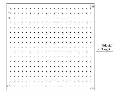
In the experiments, a six degree of freedom (6DOF) collaborative robot arm operating under position control mode was used to insert a peg into a series of 80 coplanar holes laid out in a grid, see Fig. 1. The insertion was considered successful (Pass) if the peg was fully inserted into the hole with a force at the tool center tip less than 17 N; otherwise, it was considered a Fail.
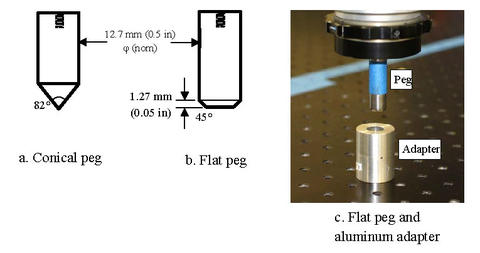
Prior to each experiment, the peg was manually inserted into each hole to measure the pose of the peg in the robot frame; the peg pose was the XYZ location of the peg tip and the orientation of the peg relative to the robot origin. These measurements are called the Raw measurements, and a total of 17 x 21 or 357 (277 fiducials and 80 targets) locations were measured, see Fig. 2. The locations of the these 357 points are also known in the world coordinate frame.
As stated earlier, the RRBC method uses the fiducial measurements, in world coordinate frame, to determine the corrections to the fiducial locations to restore the rigid body condition. The corrections to the target locations in the world frame were then estimated using eight corrected, neighboring fiducials.
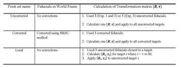
In the experiments, the points in the world coordinate frame was transformed to the robot coordinate frame using fiducials measured in both coordinate frames to obtain the transformation matrix {R, τ}. Three transformations were performed (see Table 1) on the target points:
- Transformation which utilized fiducials measured in the world frame with no corrections applied. The transformed target points are called Uncorrected points and are the result of a conventional registration process. Uncorrected fiducials were used in the registration process, and they encompassed the work volume and were widely distributed as is good practice.
- Transformation which utilized fiducials measured in the world frame which were corrected by the RRBC method. The transformed target points are called Corrected Points. Corrected fiducials were used to in the registration process.
- Transformation which utilized local fiducials measured in the world frame with no corrections applied. The transformed target points are called Local Points.Local fiducials are fiducials that are closest to a target; the transformation for each target is, therefore, unique. Like the set of Uncorrected Points, Local Points are the result of a conventional registration process with the difference being the fiducials used for registration.
Table 1. Point Sets and Type of Registration.
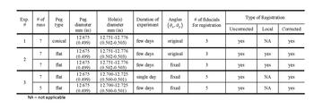
As stated earlier, the holes were coplanar and no corrections were made to the orientation angles of the peg. However, two sets of angles were used in the experiments: Original and Fixed. Original angles were the Raw measured angles and Fixed angles were the average of 357 measurements and were used for all target locations. A summary of the experimental parameters is given in Table 2.
Table 2. Summary of Parameters in Experiments.
The experiment involved 1) uploading various sets of coordinates (raw, uncorrected, corrected, and/or local) to the robot controller, 2) having the robot move to the first position specified in the raw file, 3) inserting the peg into the hole, 4) extracting the peg, and 5) moving to a position slightly above the hole. These steps were then repeated at the same position using the uncorrected, corrected, and/or local values. After the raw, uncorrected, corrected, and/or local insertions were attempted, the robot moved to the next specified position and repeated the insertions until all specified positions were evaluated.
The results for the raw insertions serve as a baseline for the other insertions as there should be no failures for the raw insertions. Any failures are due to measurement noise and robot drift as raw points are neither corrected nor transformed and are measured in the robot frame.
Publications:
1. A NIST Internal Report (NISTIR) 8198, Improving Automated Insertion Applications by Restoring Rigid-Body Condition in Point-Based Registration; http://dx.doi.org/10.6028/NIST.IR.8198r1
2. A conference paper in the Eighth International Precision Assembly Seminar, Chamonix, France, January 2018, Improving Rigid-Body Registration Based on Points Affected by Bias and Noise;
3. A NIST Internal Report (NISTIR) 8180, Method to Improve Point-Based Registration by Restoring Rigid-Body Condition; http://dx.doi.org/10.6028/NIST.IR.8180
Data:
The format of the input files was (Target name, x, y, z, ϑx, ϑy, ϑz) for all target positions where (x, y, z) are either the raw, uncorrected, corrected, or local positions in millimeters and (ϑx, ϑy, ϑz) were either Original angles (raw measured values for a given position) or Fixed angles in degrees. The coordinates of points in these files are in robot frame.
The input files Exp-1_Runs1-7.xlsx, Exp-2_Runs1-7.xlsx, and Exp-3_Runs1-12.xlsx for Experiments 1 to 3, respectively, contain several worksheets:
- All Raw Meas, Exp. i, Runs 1-j: contains the raw measurements for all 357 points (277 fiducials and 80 targets) for Experiment i. j = 7 for Exp. 1 and 2 and 12 for Exp. 3.
- Uncor-Orig: target points transformed using conventional registration; original angles.
- Uncor-Fixed: target points transformed using conventional registration; fixed angles.
- Cor-Orig: target points transformed using RRBC method; original angles.
- Cor-Fixed: target points transformed using RRBC method; fixed angles.
- Local-Orig: target points transformed using conventional registration and neighboring fiducials; original angles.
- Local-Fixed: target points transformed using conventional registration and neighboring fiducials; fixed angles.
- Raw-Orig: no transformation – target points as measured in robot frame; original angles.
- Raw-Fixed: no transformation – target points as measured in robot frame; fixed angles.
Depending on the experiment, the input files may only contain a subset of the above listed worksheets.
The Pass/Fail information for all experiments and for all runs are given in a file named Fail_Locations.xlsx. In this file, a ‘0’ indicates a Pass insertion and a ‘1’ indicates a Fail insertion. The file contains the following four worksheets:
- Exp. 1 - Orig. Angles: Experiment 1, original angles. Insertions were not performed for Raw target points in Runs 1 – 3.
- Exp. 2 - Orig. Angles: Experiment 2, original angles
- Exp. 2 - Fixed Angles: Experiment 2, fixed angles
- Exp. 3 - Fixed Angles: Experiment 3, fixed angles
Please reference our DOI https://doi.org/10.18434/T4/1500929 when using our data for research and/or publications.