U.S. flag

An official website of the United States government

Official websites use .gov
A .gov website belongs to an official government organization in the United States.

Secure .gov websites use HTTPS
A lock ( ) or https:// means you’ve safely connected to the .gov website. Share sensitive information only on official, secure websites.

NCAL: Diffraction Stress Measurement Under Applied Load

Summary

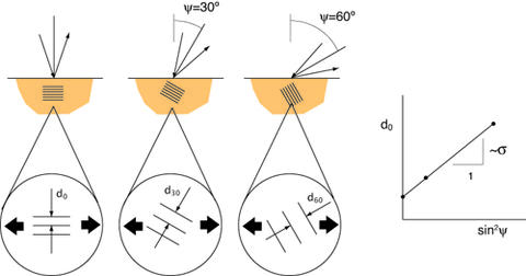
Diffraction-based stress measurements are powerful techniques that can be used to measure the residual and applied stresses in a material under loading . This method measures the spacing between layers of atoms and tracks the spacing as it expands or contracts in response to force.  The NIST Center for Automotive Lightweighting (NCAL) employs this technique for stress measurements that are difficult to determine from simple force-over-area calculations such as those in multiaxial deformation, uniaxial testing beyond uniform deformation, or inside an individual crystallite. 

Description

Using X-ray diffraction (XRD) techniques one can measure the full stress tensor just inside the surface of a sheet metal specimen under applied loading.  This permits the measurement of biaxial stress states resulting from directly applied deformation (see NCAL: Multiaxial Material Performance) or resulting from features such as a hole or localized neck.  Measurements can be made even when the test method cannot measure the stress directly, due to unquantifiable friction (such as in the Forming Limit Press), complex specimen designs (cruciform testing and octostrain testing), and/or highly anisotropic sheet materials that have strong crystallographic texture owing to rolling mill processing.   

XRD is commonly used to measure a material’s crystal structure, crystal lattice orientation, and the spacing of the lattice planes.  NCAL’s XRD systems are designed to measure the spacing of one or two specifically selected lattice plane reflections for a given material. By tilting the measurement system from the normal direction of the sheet toward the direction of loading the distribution of strains can be measured and used to derive the full stress tensor just inside the sheet surface. In addition to the work in NCAL, we also have a close collaboration with the staff who operate the neutron diffractometer at NIST Center for Neutron Research (NCNR) beamline BT-8.

Spacing between lines representing atomic planes are shown as increasing as the x-ray diffraction system tilts to be more co-aligned with the loading axis
Credit: Mark Iadicola


Rigorous methods are applied by NCAL staff to ensure that quantitative XRD stress measurements are reliable in light of the many difficulties inherent in this measurement problem. The most significant challenge relates to the texture of industrial sheet metals, which affects the distribution of grain orientations within the XRD sampling volume and, thereby, influences the computed stress values. As the sheet is deformed to higher plastic strains, the initial texture evolves, further complicating the determination of accurate stresses.

The most accurate method to convert the lattice strain measurements to stresses is to perform calibration experiments on each material to determine the set of X-ray elastic constants  (XEC) that apply to a given range of plastic strains and strain states. Calibration experiments consist of comparing XRD stresses against those determined by conventional force-over-area calculations in uniaxial experiments at equivalent applied strain levels. 

This effort has been worked on in close collaboration with colleagues from the NCNR, which allows us to cross-compare  surface XRD stresses with more-penetrative neutron diffraction measurements. We also collaborate on the development of computational models that account for texture effects on diffraction data to avoid the more rigorous but time-consuming calibration methods.

We apply XRD to measure the stress tensor on biaxial deformation experiments.  Measurements are performed at multiple increments in the plastic range while the specimen is held under constant load. XRD systems can be attached to our forming limit press, cruciform, and octostrain mechanical testing machines.  The measurements are made over a surface area typically between 0.5 mm to 4 mm in diameter, the XRD systems can be repositioned to interrogate multiple points on the specimen surface.  This permits measurements of the multiaxial stress field around features (e.g. hole or localized neck) in the specimen.  Industrial stakeholders are interested in these measurements because these multiaxial stresses typically can only be approximated through a numerical model using an assumed constitutive law.

An additional application of XRD measurements is to extract valid stress-strain data beyond the ultimate tensile stress of the material (onset of necking).  A major limitation of the standard uniaxial tensile test (e.g. ASTM E8/E8M or ISO 6892-1) is that once the material reaches the maximum force (ultimate tensile stress), the specimen undergoes a mechanical instability where the deformation concentrates to a localized area and forms a neck.  Although the specimen continues to plastically deform, the stress can no longer be determined from force-over-area calculations since the area is no longer uniform along the gauge length.  However, stress-strain data beyond this “uniform elongation” limit are often desired for modeling industrial applications such as metal forming.  Mathematical formulas have been devised to extrapolate stress-strain curves beyond localization, but they utilize unsupported assumptions such as constant (uniaxial) state of stress and constant volume deformation (i.e. voids are neglected).

Using digital image correlation (DIC) combined with our XRD stress measurement method, the goal of this project is to determine the local neck strain limit where off-axis stress components become large enough that they invalidate the uniaxial stress assumption. While our equipment can provide valid measurements within a necking tensile specimen up to the true strain at failure, establishing new uniaxial stress limits, using only local DIC strain measurements could enable mechanical testing labs to obtain high quality data beyond the current limits set by existing standard test methods. Further, we intend to use the measured data to test the validity of theoretical correction factors proposed to correct for multiaxial stress during necking to determine the equivalent uniaxial behavior.

One of the limitations of traditional XRD (and Neutron at NCNR) stress measurements is that they typically average stress measurements over a large area compared to the microstructure.  To investigate individual portions of the microstructure, different techniques are needed.  One example is the Hard X-ray Microscopy beamline at the European Synchrotron Radiation Facility.  This beamline allows nondestructive analysis of the local rotation and lattice strain inside individual crystallites of a material.  


We have recently worked to develop an in-situ loading stage and DIC capabilities to measure materials as they deform.  We have applied these measurements to structural materials and phase transforming materials, and plan to expand on these measurements in the future.  Through the Commission on Diffraction Microstructure Imaging at the International Union of Crystallography (IUCr) we have also participated in discussion of reference materials for this length scale.

Created February 22, 2013, Updated August 20, 2025
Was this page helpful?