
Official websites use .gov
A .gov website belongs to an official government organization in the United States.
Secure .gov websites use HTTPS
A lock (
) or https:// means you’ve safely connected to the .gov website. Share sensitive information only on official, secure websites.
Gas Flow Standards
Summary
NIST's gas flow meter calibrations support a wide range of industries that require low-uncertainty, SI-traceable measurements. These industries include semiconductor fabrication, the Department of Defense, aerospace, automotive, manufacturing, power generation, natural gas custody transfer, flow calibration laboratories, and flow meter manufacturers. Calibrations are performed by collecting gas from the meter under test into a collection vessel, and the mass accumulated over a measured time interval is used to determine the flow.
The Fluid Metrology Group (FMG) uses two types of primary standards: Pressure-Volume-Temperature-time (PVTt) and Rate-of-Rise (RoR). Both types of standards rely on the volumetric principle to determine mass flow, requiring accurate measurement of the collection vessel's internal volume prior to calibrating flow meters. During calibration, the accumulated mass is determined by measuring gas temperature and pressure in the vessel and applying an equation of state to calculate the density. The mass of gas collected is then determined by multiplying the gas density by the collection vessel volume. These standards are used to calibrate NIST working standards, which are secondary standards that include laminar flow elements, critical flow venturis, and gas turbine meters. The working standards allow the FMG to achieve much higher flows than the primary standards alone as shown in Fig. 3.
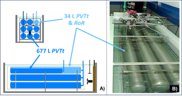
Figure 1 illustrates NIST’s two PVTt standards, with nominal collection vessel volumes of 34 L and 677 L, respectively. These standards are housed in a recirculating water bath, facilitating low-uncertainty temperature measurements of the gas collected in the vessels. The 677 L collection vessel consists of an array of eight cylindrical tubes, while the 34 L collection vessel uses a single cylindrical tube and functions both as a PVTt system for larger flows and as a RoR standard for lower flows.
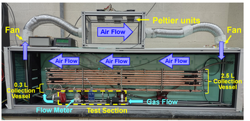
The Semiconductor Low Flow Standard (SLowFlowS), shown in Figure 2, comprises NIST’s two smaller RoR systems with nominal volumes of 0.3 L and 2.5 L, respectively. The RoR vessels in SLowFlowS are comprised of long, slender tubes for enhanced heat transfer, with 2 tubes for the 0.3 L system and 16 tubes for the 2.5 L system. The collection vessels in SLowFlowS are thermostatted with air instead of water to reduce the risk of corrosion and enhance safety, as the system is designed for use with both flammable and inert gases.
Description
While both the PVTt and RoR methods are volumetric, the PVTt method is a static volumetric method meaning that the pressure and temperature measurements are made under static conditions. In contrast, the RoR method requires these measurements to be made dynamically while gas accumulates in the collection vessel. Both methods require the volume of the collection vessel to be known and an equation of state for the gas species. The thermophysical property reference database, REFPROP is used.
When using the PVTt method, we begin by evacuating the gas in the collection vessel until a specified pressure is reached. Once the collection vessel reaches the desired pressure, we close the valve to the vacuum pump and wait for the remaining gas to reach thermal equilibrium before measuring its initial pressure and temperature. From these measurements, we determine the initial gas density and, subsequently, the initial mass in the collection vessel. While the gas in the collection vessel is evacuating, we simultaneously establish a steady flow through the flow meter being calibrated, directing the discharge through a bypass valve vented to the roof. To initiate flow collection, a diverter system is used to redirect the flow from the bypass to the collection vessel until a specified pressure is attained. Once this pressure is reached, the valve to the collection vessel closes, and the flow is redirected back to the bypass. We then wait for the gas in the collection vessel to reach thermal equilibrium before recording the final pressure and temperature, which allows us to determine the density and final mass. The difference in mass (final minus initial), divided by the collection time, gives the mass flow. A symmetric diversion process or connecting volume mass cancelation procedure is implemented to ensure that density changes in the connecting volume between the flow meter and the collection vessel are negligible.
In the RoR method, gas pressure and temperature in the collection vessel are measured at specified time intervals as steady flow from the flow meter being calibrated accumulates in the vessel. At each time interval, the pressure and temperature measurements are used to calculate the gas density, which is then multiplied by the collection vessel volume to determine the mass. A set of discrete time and mass data points is obtained. Since the mass flow from the flow meter is constant, the mass increase in the collection vessel is linear. A least squares linear regression is then applied to find the slope of the best-fit line to the mass versus time data. This slope represents the mass flow.
Key advantages of the RoR method over the PVTt method include:
- No diverter valve system is required, as mass is determined during the filling process.
- Faster collection times for "low" flows, as mass is calculated at each time interval, rather than waiting to fill the vessel to the required pressure to implement the PVTt connecting volume mass cancelation procedure
One challenge of the RoR method is accurately measuring the temperature during the filling process. As gas enters the collection vessel, it compresses the existing gas, causing a temperature increase and resulting in a transient, spatially non-uniform temperature distribution. The NIST RoR flow standard, SLowFlowS, addresses this challenge with a novel collection tank design that effectively dissipates energy from compression through conduction to the vessel walls. This newer design allows SLowFlowS to handle a wider flow range with lower uncertainty over most of the flow range compared to the 34 L RoR, as illustrated in Fig. 3.
NIST's primary gas flow standards are used to validate new gas flow standards developed by the FMG and are regularly validated through key comparisons with other National Metrology Institutes.
Measurement services
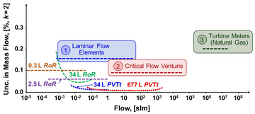
Figure 3 illustrates the flow range (in standard liters per minute, slm) of five NIST primary gas flow standards, plotted against the uncertainty in mass flow. The dashed lines (----) represent each standard. As shown in the figure, the standards were intentionally designed with overlapping flow ranges to facilitate direct comparisons and periodically validate their performance. Together, these five primary standards cover 8 decades of flow.
The low uncertainty of the primary standards is critical for accurately investigating the underlying physics of flow meters, including laminar flow elements (LFEs), critical flow venturis (CFVs), and turbine meters. By combining the fluid dynamic principles of these flow meters with state-of-the-art measurements, we can extend their operational range by accounting for species effects, ambient temperature effects, and other necessary corrections. As shown in the figure, we use these flow meters as working gas flow standards (WGFS) to calibrate customer flow meters, along with our primary standards. We leverage our understanding of the physics of our WGFS by orienting these flow meters in a parallel configuration to "bootstrap" to larger flows that exceed the capacity of our primary flow standards, as illustrated in Fig. 3. By combining our five primary standards and three types of secondary WGFS, we provide SI traceability for flow across 13 decades of flow.
Scientific Opportunities/Applications
Temperature effects on flow meters
Species effects on flow meters
Real gas effects on Critical Flow Venturis
Calibration services
Flow metrology