
Official websites use .gov
A .gov website belongs to an official government organization in the United States.
Secure .gov websites use HTTPS
A lock (
) or https:// means you’ve safely connected to the .gov website. Share sensitive information only on official, secure websites.
Aquatic Vehicle Tests

Development of Standard Test Methods for Underwater Remotely Operated Vehicles
Background
The National Institute of Standards and Technology, Engineering Laboratory, Intelligent Systems Division, is developing the measurement and standards infrastructure necessary to evaluate robotic capabilities for emergency responders and military organizations addressing critical national security challenges. This includes leading development of a comprehensive suite of ASTM International Standard Test Methods for Response Robots that includes more than 50 test methods for remotely operated ground, aerial, and maritime systems. Several different civilian and military sponsors have supported this effort. And the test methods have been replicated and used in dozens of locations worldwide to measure and evaluate response robot capabilities to meet the following objectives:
- Facilitate communication between user communities and commercial developers, or between development program managers and performers, by representing essential capabilities in the form of tangible test apparatuses, procedures, and performance metrics that produce quantifiable measures of success.
- Inspire innovation and guide developers toward implementing the combinations of capabilities necessary to perform essential mission tasks.
- Measure progress, highlight break-through capabilities, and encourage hardening of developmental systems through repeated testing and comparison of quantitative results.
- Inform purchasing and deployment decisions with statistically significant capabilities data. To date, the suite of ground robot test methods have been used to specify more than $60M worth of robot procurements for military and civilian organizations performing C-IED missions.
- Focus operator training and measure proficiency to track very perishable skills over time and enable comparison across squads, regions, or national averages. To date, the suite of ground robot test methods have been used by more than 250 civilian and military bomb technicians.
The suite includes 15 draft standard test methods for underwater remotely operated vehicles (UROV) that measure essential capabilities for countering improvised explosive devices (C-IED) and other hazardous underwater tasks. These repeatable tasks are conducted in various orientations, floating on the water surface, or on the tank bottom. When conducted in mobile frac tanks or swimming pools, the clear water and multiple video angles provide key insights into the capabilities of the systems. This enables measurement of baseline system capabilities and operator proficiency before adding the complexity of environmental variables one at a time, such as turbulence, darkened conditions, and/or turbidity. For example, multiple submerged water pumps surround each test apparatus to provide constant turbulence while performing the tasks. This encourages automatic holding of position and orientation to improve performance. A blackout tarp over the top of the tank provides darkened conditions. Beyond the obvious training benefits, these test methods provide useful de-bugging tools and readiness assessments after repairs prior to performing the same tests within more operationally relevant waters during training exercises
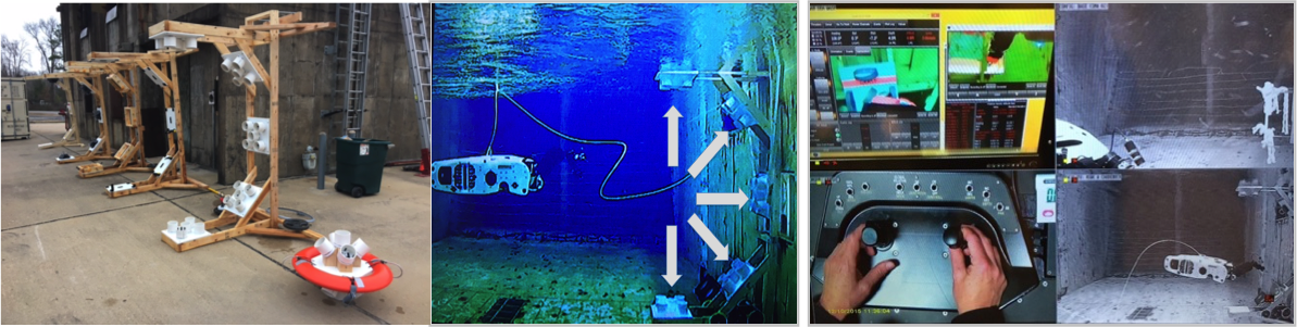
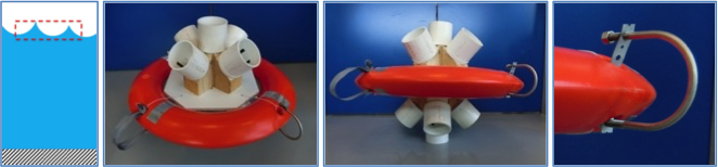
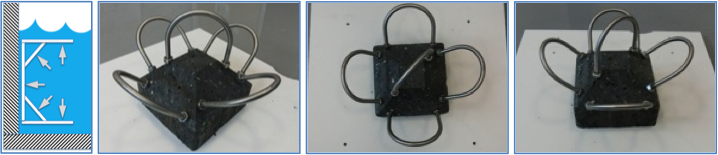
Figure 1: A) Several of the underwater test methods are mounted to submerged C-frame apparatuses. B) The apparatus presents 5 different task panel orientations to the UROV, including +90°upward, +45°upward, 0° forward, -45° downward, -90° downward. They can be performed in any order, presumably from easiest to hardest, within time limited trials to determine an average rate of completion. C) Multiple cameras capture all the action around the test apparatus and at the remote operator station, including 2 views of the UROV, operator station screen, and operator hand motions.
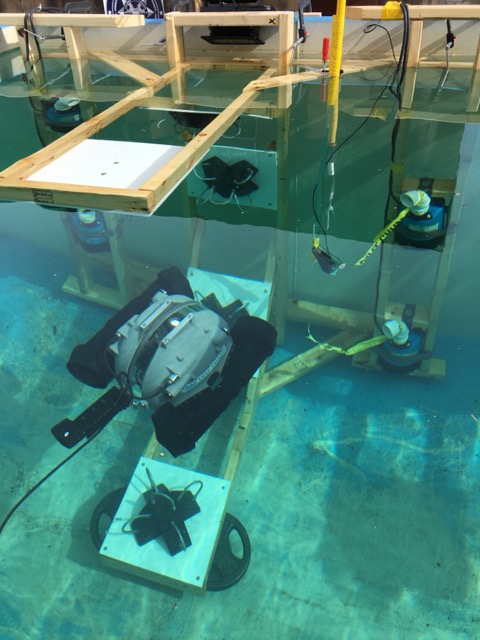
Figure 2: Each test method can include multiple submerged water pumps on both side of the apparatus to jostle and push the UROV during the task at every depth. These pumps continuously force the UROV from its desired position and orientation requiring constant, preferably automatic, station keeping capabilities to perform each task effectively.
Definition of Response Robot Includes UROVs
The working definition of a “response robot” is a remotely deployed device intended to perform operational tasks at operational tempos. It should serve as an extension of the operator to improve remote situational awareness and provide means to project operator intent through the equipped capabilities. It should also improve effectiveness of the mission while reducing risk to the operator. Key features include:
- Rapidly deployed
- Remotely operated from an appropriate standoff
- Maneuverable in complex environments
- Sufficiently hardened against harsh environments
- Reliable and field serviceable
- Durable or cost effectively disposable
- Equipped with operational safeguards
Difference Between a “Standard Test Method” and a “Standard Robot”?
Standard test methods are simply agreed upon ways to objectively measure robot capabilities. They isolate certain robot requirements and enable repeatable testing. They are developed and validated through a consensus process with equal representation of users, developers, and test administrators. In the case of UROV systems, one key standards committee is the ASTM International Standards Committee on Unmanned Maritime Vehicle Systems (F41). The resulting robot capabilities data captured within standard test methods can be directly compared even when the tests are performed at different sites at different times. They help establish confidence in a robot and remote operator’s ability to reliably perform particular tasks. Each standard test method includes the following elements:
- Apparatus (or prop): A repeatable, reproducible, and inexpensive representation of tasks that the system is expected to perform. The apparatus should challenge the system with increasing difficulty or complexity and be easy to fabricate internationally to ensure all robots are measured similarly.
- Procedure: A script for the system operator to follow (along with a Test Administrator when appropriate). These tests are not intended to surprise anybody. They should be practiced to refine designs and improve techniques.
- Metric: A quantitative way to measure the capability. For example, completeness of 10 continuous repetitions of a task or distance traversed within an environmental condition, etc. Together with the elapsed time, a resulting rate in tasks/time or distance/time can be calculated.
- Fault Condition: A failure of the robotic system preventing completion of 10 or more continuous repetitions. This could include a stuck or disabled vehicle requiring maintenance, or software issues at the remote operator control unit. All such failures are catalogued during testing to help identify recurring issues.
A “standard robot” is a completely different concept and should be carefully considered. A standard robot would presumably meet a well-defined equipment specification for size, shape, capabilities, interfaces, and/or other features. Such equipment standards are typically intended to improve compatibility, enable interoperability, increase production, lower costs, etc. This can be important for many reasons, but can also hinder innovation. In this effort, we are not proposing to develop a standard UROV specification of any kind. Rather, we are proposing to develop standard test methods that can be used to evaluate and compare entire classes of such systems in objective and quantifiable ways. The resulting suite of standard test methods could indeed be used to specify a standard UROV at some point, similar to how they are used to specify purchases. But that is left to each user community to define for themselves based on their particular mission objectives. We use standard test methods to encourage implementation of new technologies to improve capabilities and measure progress along the way.
Approach
Our process for developing, validating, standardizing, and disseminating these test methods involves several types of events:
- Test method development workshops to decompose mission requirements into suites of elemental test methods. These events define the initial apparatuses, procedures, and performance metrics necessary to capture baseline capabilities. They also define an approach toward controlling environmental variables and then implementing such variables individually, such as water clarity, lighting, turbulence, current, etc. For example, water turbulence is introduced around the test apparatuses using submerged pumps to challenge “auto-pilot” station-keeping capabilities while performing precise dexterity tasks. Test method development workshops often involve the relevant standards committees. In this case, that could be the ASTM International Standards Committee on Unmanned Maritime Vehicle Systems (F41),
- Validation exercises with developers and user communities. These somewhat public events exercise the tangible test apparatuses with repeated testing of different UROV systems to facilitate bi-directional communication between the communities. This helps cut through the inevitable marketing, even within development programs. These events determine if the test methods appropriately challenge the state-of-the-science as intended, and that they adequately measure and highlight “best-in-class” capabilities to inform/align expectations for user communities.
- Comprehensive capability assessments for developmental or commercial systems. These private evaluations test specific system configurations across all applicable test methods. This involves typically more than 20 test methods when considering testing all sensors, thrust, endurance, latency, etc. in addition to maneuvering, dexterity, situational awareness, etc. All the applicable environmental variables are also tested individually. So-called “expert” operators provided by the developer are used to capture the best possible performance. The resulting data enables direct comparison of capabilities and trade-offs while helping to establish the “repeatability” and “reproducibility” of the test methods for the standardization process. Test trials are conducted to statistical significance up to 10, 20, or 30 repetitions depending on the number of failures. The objective is typically 80% reliability with 80% confidence but test sponsors can adjust these thresholds depending on envisioned mission resilience to failure. Such capabilities data across an entire class of similar robots provides objective comparisons to support purchasing decisions.
- Operator training with standard measures of proficiency. These events typically include 10 basic skills tests for maneuvering, dexterity and situational awareness. Different user communities can define their own training suites using different combinations of test methods. Training trials are time limited to 5 or 10 minutes each so they are quick and focused. Novices and expert operators work for similar times within each test method and across the entire suite to normalize fatigue. For example, 10 tests take 100 minutes plus some time for transitions. Some tests can be longer or shorter. The objective is to test long enough to establish a rate of successful task completions. Operators can then compare their rate of success to that of the “expert” provided by the system developer. This is presumably the best ever operator score which sets to 100% of proficiency. Different user communities can use this process to set their own thresholds of acceptability for deployment. Example categories for eventual certification could include Novice: 0–39%, Proficient: 40–79%, Expert: 80–100%. Complete circuit training can typically be conducted in 1-2 hours, alone or in groups, performing timed trials with synchronized rotations from test to test.
- Robot competitions with academic and commercial robot developers. Robot competitions introduce prototype and standard test apparatuses as tangible descriptions of robot requirements captured from various user communities. The test apparatuses guide innovation while providing inherent measures of progress. Competitions can include up to 100 test trials with a wide variety of robotic approaches on display, making them ideal for refining standard test apparatuses and procedures. Emerging robot capabilities can be quantified and “Best-In-Class” approaches highlighted. Competitions help quicken the pace of development of the standard test methods while inspiring innovation so have become a main driver of our process. They also act as incubators for test administrators to learn to fabricate and administer the latest test methods.
Initial Test Method Suite
The suite of test methods for UROVs includes the following:
1. Configuration Identification including size, weight, packaging, setup time, pictures of configuration details (dry).
2. Bollard thrust measures the pulling force with zero velocity for 30 seconds. Note: the manufacturer should provide a mounting point on the UROV rear chassis (all sides ideally).
3. Sonar acuity is measured using planar, angular, and cylindrical targets at a known distance. It is conducted while attached to the Bollard Thrust sensor line to accurately set the range to target. Sonar readings will be photographed or captured within the system with zero thrust and at full thrust to incite vibrations.
4. Pose agilities to demonstrate controlled maneuverability including translate (Tx,y,z), rotate (Rz), pitch (Rx), and roll (Ry) to specified angles.
5. Camera pointing and zooming to identify visual acuity targets at ranges from near field 40cm (16 in) to far field 3-6m (10-20 ft) alternately. This test is performed with any collection of system cameras as an indicator of omni-directional situational awareness. But the level of acuity is part of the evaluation. So using the best cameras is advised.
6. Grasp strength to resist extracting a seat belt strap from a closed gripper will be conducted when removed from the tank after testing.
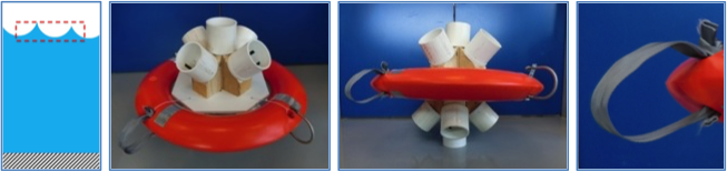
7. Inspect Floating Objects: Below Water Line (10 minute time limit):
The purpose of this test is to evaluate the maneuvering and camera pointing capabilities of the system below the water line by performing a series of tasks to inspect targets from multiple angles. This test is conducted on the water surface. It should be performed in still water and with turbulence to challenge auto station-keeping capabilities.
- Start 2m (6ft) from the designated task location on the water surface.
- Inspect below the water line inside downward facing pipes 10cm (4in) in diameter x 10cm (4in) deep to correctly identify the number of randomly placed bars 1.2cm (0.5in) wide x 5cm (2in) long on the inner surface. Capture images of each to verify, if possible.
- Repeat in any order to completely identify the set until time expires. If completed, start identifying a second set in any order.
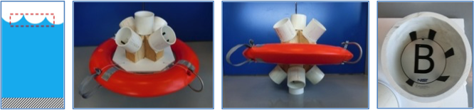
8. Inspect Floating Objects: Above Water Line (10 minute time limit):
The purpose of this test is to evaluate the maneuvering and camera pointing capabilities of the system above the water line by performing a series of tasks to inspect targets from multiple angles. This test is conducted on the water surface. It should be performed in still water and with turbulence to challenge auto station-keeping capabilities.
- Start 2m (6ft) from the designated task location on the water surface.
- Inspect above the water line inside upward facing pipes 10cm (4in) in diameter x 10cm (4in) deep to correctly identify the number of randomly placed bars 1.2cm (0.5in) wide x 5cm (2in) long on the inner surface. Capture images of each to verify, if possible.
- Repeat in any order to completely identify the set until time expires. If completed, start identifying a second set in any order.
9. Grasp Floating Objects (10 minute time limit):
The purpose of this test is to evaluate the maneuvering, dexterity, and gripper strength capabilities of the system by performing a series of tasks to grasp soft features of a floating object and tow some distance. This test is conducted on the water surface. It should be performed in still water and with turbulence to challenge auto station-keeping capabilities.
- Start 2m (6ft) from the designated task location on the water surface.
- Grasp at water level a soft strap made of seat belt loops 10cm (4in) in diameter and drag the object 5m (15 ft) into a designated end zone.
- Release and grasp the opposite soft strap and drag back to start zone.
- Repeat until time expires.
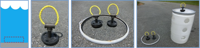
10. Hook Floating Objects (10 minute time limit):
The purpose of this test is to evaluate the maneuvering, dexterity, and tool deployment capabilities of the system by performing a series of tasks to hook carabiners to a floating object as a mock attachment of a remote pull line. This test is conducted on the water surface. It should be performed in still water and with turbulence to challenge auto station-keeping capabilities.
- Start 2m (6ft) from the designated task location on the water surface.
- Hook at water level a carabiner to a D-ring 10cm (4in) in diameter leaving the carabiner attached without the associated remote pull line.
- Repeat by returning to the nearby tether wrangler for additional carabiners. The timer will pause during the return transit and grasping. After grasping the carabiner, if it is dropped time will continue to elapse
- Repeat until time expires.
11. Relocate Bottom Objects (10 minute time limit):
The purpose of this test is to evaluate the maneuvering, dexterity, gripper strength, towing, and precision placement capabilities of the system by performing a series of tasks to relocate weighted objects onto a mock transition buoy. This test is conducted on the tank bottom. It should be performed in still water and with turbulence to challenge auto station-keeping capabilities.
- Start 2m (6ft) from the designated task location on the tank bottom.
- Grasp one weighted T-handles with rope loops 10cm (4in) diameter (of two prepositioned in the task location)
- Transit 5m (15ft) and approach the elevated task location 1m (3ft) above the tank bottom.
- Place the weighted T-handle within the elevated task location 0.6m (2ft) diameter (next to another T-handle).
- Grasp the other weighted T-handle and return it to the designated task location on the tank bottom.
- Repeat the grasp, transit, place tasks until time expires.
- Maximum working weight may be chosen by the operator. If the object touches the tank bottom or water surface between the two locations the repetition will not count and time will elapse. This penalty will reduce the average number of successful tasks completed per minute.
12. Inspect Targets (5 minutes per orientation, 25 minutes maximum):
The purpose of this test is to evaluate the maneuvering, camera pointing, and disruptor aiming capabilities of the system by performing a series of tasks to inspect or aim at targets from multiple angles. This test is conducted within a C-frame apparatus affixed to the side wall of the tank with 5 different task orientations to be performed in any order chosen by the operator. It should be performed in still water and with turbulence to challenge auto station-keeping capabilities (Note: if aiming disruptors, bulls-eye targets replace the lettering).
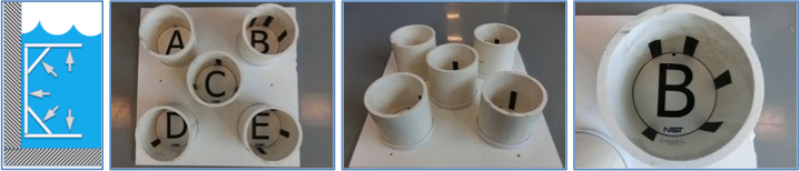
- This test is conducted within a C-frame apparatus affixed to the side wall of the tank with 5 different task orientations to be performed in any order chosen by the operator. It should be performed in still water and with turbulence to challenge auto station-keeping capabilities.
- Start 2m (6ft) from the apparatus and approach the chosen task orientation.
- Inspect inside pipes 10cm (4in) in diameter x 10cm (4in) deep to correctly identify the number of randomly placed bars 1.2cm (0.5in) wide x 5cm (2in) long on the inner surface. Capture images of each to verify, if possible.
- Inspect all 5 pipes in any order without repeating. If completed, start identifying a second set in any order. Repeat until time expires.
- Reset the timer and move on to a different orientation.
- Repeat until all possible orientations are complete.
13. Cut Ropes (5 minutes per orientation, 25 minutes maximum):
The purpose of this test is to evaluate the maneuvering, dexterity, and tool deployment capabilities of the system by performing a series of tasks to cut ropes from multiple angles. This test is conducted within a C-frame apparatus affixed to the side wall of the tank with 5 different task orientations to be performed in any order chosen by the operator. It should be performed in still water and with turbulence to challenge auto station-keeping capabilities
- Start 2m (6ft) from the apparatus and approach the chosen task orientation.
- Cut ropes of a diameter and type chosen by the administrators, for example 12mm (1/2in) diameter poly, bungee cords, 550 line and others. Cut all 5 directions on a given panel.
- Reset the timer and move on to a different orientation.
- Repeat until all possible orientations are complete.
14. Hook Carabiners (5 minutes per orientation, 25 minutes maximum):
The purpose of this test is to evaluate the maneuvering, dexterity, and tool deployment capabilities of the system by performing a series of tasks to hook carabiners from multiple angles as a mock attachment of a remote pull line. This test is conducted within a C-frame apparatus affixed to the side wall of the tank with 5 different task orientations to be performed in any order chosen by the operator. It should be performed in still water and with turbulence to challenge auto station-keeping capabilities
- Start 2m (6ft) from the apparatus and approach the chosen task orientation.
- Hook a carabiner to a D-ring 10cm (4in) diameter leaving the carabiner attached without the associated remote pull line.
- Repeat by returning to the nearby tether wrangler for additional carabiners. The timer will pause during the return transit and grasping. After grasping the carabiner, if it is dropped time will continue to elapse.
- Approach the same task orientation and hook to a different D-ring. (a faster implementation of this test includes hooking the carabiner to the center D-ring and then grasping the remaining 4 orientations with the gripper).
- Repeat until time expires.
- Reset the timer and move on to a different task orientation.
- Repeat until all possible orientations are complete.
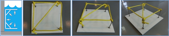
15. Affix/Aim Disruptors from Multiple Orientations (5 minutes per orientation)
The purpose of this test is to evaluate the maneuvering, dexterity, and tool deployment capabilities of the system by performing a series of tasks to affix and point disruptors from multiple angles. This test is conducted within a C-frame apparatus affixed to the side wall of the tank with 5 different task orientations to be performed in any order chosen by the operator. It should be performed in still water and with turbulence to challenge auto station-keeping capabilities.
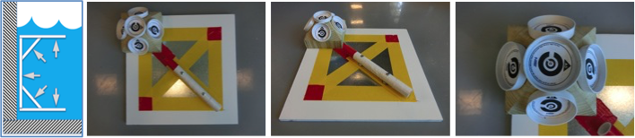
- Start 2m (6ft) from the apparatus and approach the chosen task orientation.
- If equipped with a disruptor, aim at all 5 bulls-eye targets on the mock hazardous device in any order. A simpler version of this aiming apparatus is also available with all targets on the task panel.
- If not equipped with a disruptor, affix the magnetic mock disruptor along any yellow taped line so that the red tip overlaps the red corner.
- Release the mock disruptor. Positions not overlapping the red corners are considered unsuccessful repetitions.
- Repeat by re-grasping the same mock disruptor and affix it until a set of 5 different orientations are complete or time expires. If the set is completed before time expires, continue with another set of 5 different orientations in order.
- If the disruptor is dropped (it can be tethered loosely to the wrist) re-acquire it or return to the nearby tether wrangler for a new prop. Time will continue, reducing the overall rate of competed tasks per minute.
- Repeat until time expires.
- Reset the timer and move on to a different task orientation.
- Repeat until all possible orientations are complete.
Contact Information:
Adam Jacoff - Project Leader
RobotTestMethods [at] nist.gov (RobotTestMethods[at]nist[dot]gov (link sends e-mail))
Adam.Jacoff [at] nist.gov (Adam[dot]Jacoff[at]nist[dot]gov (link sends e-mail))
301-975-4235