
Official websites use .gov
A .gov website belongs to an official government organization in the United States.
Secure .gov websites use HTTPS
A lock (
) or https:// means you’ve safely connected to the .gov website. Share sensitive information only on official, secure websites.
CHAL-AMB2018-01-MSPFPFRS
Results description for CHAL-AMB2018-01-MS - Microstructure, CHAL-AMB2018-01-PF – Phase Fractions, and CHAL-AMB2018-01-PFRS- Phase Evolution
1. Sample Positions and Orientations for Microstructure Measurements
AMB2018-01 includes multiple builds using IN625 and 15-5 powder on build plates of the nominally same composition. The builds for each material are numbered sequentially, B1, B2, etc. Each build includes four parts as shown in Fig. 1, again numbered sequentially, P1, P2, etc.
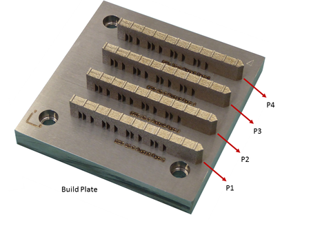
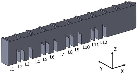
Microstructure studies were conducted on thick (nominal 5 mm) and thin (nominal 0.5 mm) legs of the as-built specimens to evaluate the sensitivity of the microstructure evolution to the local geometry and thermal conditions of the build. Specific legs are numbered as shown in Fig. 1.
Microstructure characterization measurements include 1) scanning electron microscopy (SEM) measurements, including secondary electron (SE) imaging, electron backscatter diffraction (EBSD), and energy dispersive spectroscopy (EDS), 2) synchrotron X-ray powder diffraction at beamline 11BM at the Advanced Photon Source (APS), Argonne National Laboratory (ANL), and 3) ultra-small-angle X-ray scattering (USAXS) and associated techniques at beamline 9ID-C at the APS. In addition, in situ measurements were conducted on samples that were undergoing a residual stress (RS) relief to evaluate the sensitivity of the as-built microstructure to these isothermal heat treatments. The RS relief heat treatments are 1 h at 650 °C for 15-5 steel, and 1 h at 800 °C for IN625. The USAXS measurements were conducted in situ during these RS relief heat treatments, with a time resolution of approximately 6 min. For completeness, the in situ USAXS measurements were run for at least 2 h (instead of the required 1 h) to provide additional insight into the relevant phase transformations.
2. SEM Measurements
SEM samples were cut along transverse (y-z plane) and longitudinal (x-y plane, parallel to the build plate) orientations.
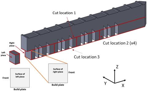
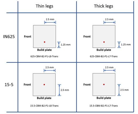
The transverse SEM specimens are made from thick legs (such as L1) and thin legs (such as L2). No specimens were made from the intermediate thickness legs. The surface of each transverse specimen was made from as close as possible to the transverse midplane of the leg. Figure 3 shows the orientations of the transverse SEM samples, with the side that was adjacent to the build plate at the bottom. The “Front” is the main visible side of the build shown in Figs. 1 and 3.
The transverse SEM specimens are listed below. For each sample the “EDS” ,“EBSD”, and "SEM Image" hyperlinks connect to a data page presented in XML format that contain links to the specific data files (“downloadURL” tag provides a web link to specific data files).
| IN625 thin leg sample: | AMB2018-01-625-CBM-B2-P1-L8-Trans | EDS | EBSD | SEM Image |
| IN625 thick leg sample: | AMB2018-01-625-CBM-B2-P1-L7-Trans | EDS | EBSD | SEM Image |
| 15-5 thin leg sample: | AMB2018-01-15.5-CBM-B2-P1-L8-Trans | EDS | EBSD | SEM Image |
| 15-5 thick leg sample: | AMB2018-01-15.5-CBM-B2-P1-L7-Trans | EDS | EBSD | SEM Image |
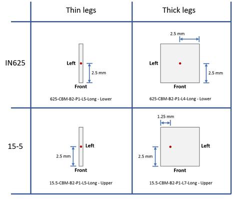
The locations on these specimens from which the SEM data were obtained are shown in Fig. 4. Note that all the measured pieces were “left pieces,” as shown in Fig. 3. Also, all SEM images are oriented so that the “Front” side of the sample is up.
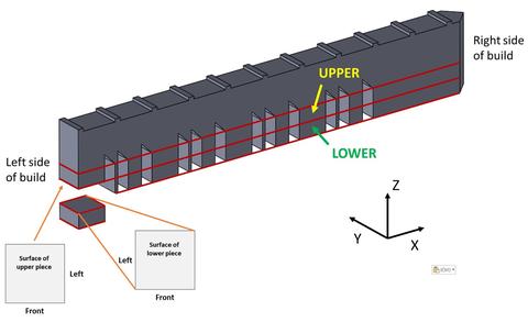
The longitudinal SEM specimens are made from thick legs (such as L1) and thin legs (such as L2). No specimens were made from the intermediate thickness legs. The surface of each longitudinal specimen was made from as close as possible to the longitudinal midplane of the leg. Figure 5 shows orientations of the thick-leg, longitudinal SEM samples. The thin-leg orientations are identical except that the cross sections are rectangular rather than square.
The longitudinal SEM specimens are listed below. The sample codes are hyperlinks that connect to the corresponding measurement data and results.
| IN625 thin leg sample: | AMB2018-01-625-CBM-B2-P1-L5-Long - Lower | EDS | EBSD | SEM Image |
| IN625 thick leg sample: | AMB2018-01-625-CBM-B2-P1-L4-Long - Lower | EDS | EBSD | SEM Image |
| 15-5 thin leg sample: | AMB2018-01-15.5-CBM-B2-P1-L5-Long - Upper | EDS | EBSD | SEM Image |
| 15-5 thick leg sample: | AMB2018-01-15.5-CBM-B2-P1-L7-Long - Upper | EDS | EBSD | SEM Image |
The locations on these specimens from which the SEM data were obtained are shown in Fig. 6. Also, all SEM images are oriented so that the “Front” side of the sample is up.
3. Powder Diffraction and USAXS Samples
All powder diffraction and USAXS samples were cut along transverse (y-z plane) orientations.
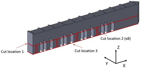
The thin transverse specimens were cut from the bridge structure as shown in Fig. 5. First, the top of the bridge was cut off using EDM (cut location 1). Second, the 8 vertical cuts were made (cut location 2), parallel to the Y-Z plane. These cuts produced four 0.5 mm thick specimens, from the transverse midplanes of the 5 mm thick legs. Finally, the legs were cut from the base plate using a single EDM cut (cut location 3). Cut-off thin legs and the specimens cut from the thick legs were used for all powder diffraction and USAXS samples. No specimens were cut from the intermediate thickness legs.
The powder diffraction and USAXS measurements are transmission X-ray measurements, so sample thickness is important for the measurements. The powder diffraction samples were thinned to approximately 100 mm and the USAXS samples were thinned to approximately 40 mm. The samples were thinned symmetrically from both sides so all powder diffraction and USAXS data were obtained from the midplane regions of the thick and thin legs.
The powder diffraction measurements provide data on the crystallographic phases present in the samples. To minimize the effect of texture, the thinned specimens were cut into many small pieces and placed in a capillary that was spun along its axis during the measurement.
The USAXS and associated measurements were conducted during in situ isothermal anneals corresponding to RS relief heat treatments. The measurement locations were as close as possible to the centers of the 5 mm × 5 mm samples.
The powder diffraction measurements were obtained from the following specimens. The sample codes are hyperlinks that connect to the corresponding measurement data and results.
| IN625 thin leg samples: | AMB2018-01-625-CBM-B1-P4-L5 |
| AMB2018-01-625-CBM-B1-P4-L11 | |
| IN625 thick leg samples: | AMB2018-01-625-CBM-B1-P4-L4 |
| AMB2018-01-625-CBM-B1-P4-L10 | |
| 15-5 thin leg samples: | AMB2018-01-15.5-CBM-B3-P1-L5 |
| AMB2018-01-15.5-CBM-B3-P4-L11 | |
| 15-5 thick leg samples: | AMB2018-01-15.5-CBM-B3-P1-L4 |
| AMB2018-01-15.5-CBM-B3-P1-L10 |
The USAXS and associated measurements were obtained from the following specimens. The sample codes are hyperlinks that connect to the corresponding measurement data and results.
| IN625 thin leg samples: | AMB2018-01-625-CBM-B1-P4-L2 |
| AMB2018-01-625-CBM-B1-P4-L8 | |
| IN625 thick leg samples: | AMB2018-01-625-CBM-B1-P4-L1 |
| AMB2018-01-625-CBM-B1-P4-L7 | |
| 15-5 thin leg samples: | AMB2018-01-15.5-CBM-B3-P1-L2 |
| AMB2018-01-15.5-CBM-B3-P1-L8 | |
| 15-5 thick leg samples: | AMB2018-01-15.5-CBM-B3-P1-L1 |
| AMB2018-01-15.5-CBM-B3-P1-L7 |
Contacts
-
(301) 975-6032
-
(301) 975-2265