
Official websites use .gov
A .gov website belongs to an official government organization in the United States.
Secure .gov websites use HTTPS
A lock (
) or https:// means you’ve safely connected to the .gov website. Share sensitive information only on official, secure websites.
Download Free CAD Models, STEP Files, and Test Results
Types of Test Cases
The FTC and CTC were part of the MBE PMI Validation and Conformance Testing Project that concluded in 2015. The FTC and CTC are not intended to represent best practice in how to apply GD&T (geometric dimensioning and tolerancing) to a part. Simpler GD&T strategies could have been used. The test cases are intended to be valid presentations of GD&T defined in the ASME Y14 tolerancing standards, some of which may not be commonly used.
The STC are modified versions of the FTC that remove some of the more complicated and less commonly used PMI, including all datum targets. The STC were developed in 2023.
These test cases are used by the CAx-IF to test implementations of STEP AP242 in CAD software.
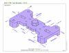
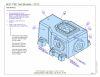
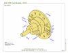
Fully-Toleranced Test Cases (FTC)
- FTC Definitions include sample STEP AP203 files of model geometry only and explanations of all PMI
- STEP AP242 and AP203 files for each FTC, many with graphical and semantic PMI
- FTC 07, 08, 09, and 10 fit together in an assembly
|
|
|
|
|
|


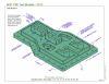
Simplified Test Cases (STC)
FTC 6-10 have been modified to create Simplified Test Cases (STC). The STC remove some of the more complicated and less commonly used PMI, including all datum targets. The geometry of the STC is the same as the corresponding FTC. STEP AP242 files for each STC are available.
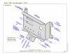
Combined Test Cases (CTC)
- CTC Definitions include sample STEP AP203 files of model geometry only and explanations of all PMI
- STEP AP242 and AP203 files for each CTC, many with graphical and semantic PMI
- The CTC are not intended to be fully toleranced. CTC 02 and 04 fit together in an assembly
|
|
|
|
|
Download CAD models
| CAD Software (NIST Disclaimer) | STC | FTC/CTC |
|---|---|---|
| Dassault Systèmes CATIA | V5-6R2023 | V5-6R2019 |
| Siemens NX | NX 2027 | NX 1980 |
| Autodesk Inventor | Inventor 2024 | Inventor 2021 |
| PTC Creo | Creo 10 | Creo 10 |
| Dassault Systèmes SolidWorks | SolidWorks MBD 2018 | |
| The STC, developed in 2023, are simplified versions of the FTC. | Older versions of FTC (6,8,9) and CTC (1-5) were verified as part of the original testing project that concluded in 2015 and documented in the Test Results below. |
Hole Test Case (HTC)
CAD models (CATIA V5, Creo, NX) for testing different types of holes (counterbore, countersink, through, depth) were developed in 2024 for testing in the CAx-IF.
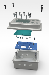
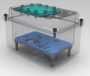
Modified Test Case (MTC)
These CAD models (NX, SolidWorks) are from the 2018 project Design, Manufacturing, and Inspection Data for a Box Assembly. The models are based on FTC-07 (box), FTC-08 (lid), and FTC-09 (plate) from above. Those FTC test cases were remodeled to be smaller, have simpler PMI, include fasteners to join the parts, and to be more easily manufactured. A fourth part was also added.
|
|
FTC and CTC Test Results
The verification and validation results from 2015 measure PMI implementation capabilities in CAD software and derivative STEP, JT, and 3D PDF files. The results are based on the test case specifications, CAD modeling methods, versions of CAD software, and comparison methodologies. PMI representation and presentation are evaluated by many verification characteristics and validation issues. The results may identify issues relevant to your use cases for downstream automated-consumption of PMI representation or human-interpretation of PMI presentation. The verification and validation testing results related to the test case PMI were generated based on older versions of the CAD systems. Issues identified for the semantic and graphic representation of PMI in each CAD system may have been (and hopefully have been) resolved since the original testing took place.
- Testing Implementations of Geometric Dimensioning and Tolerancing in CAD Software
- Guide to the CAD Models and Verification Testing Results
- Measuring the PMI Modeling Capability in CAD Systems: Report 1 - Combined Test Case Verification (Slides) - compares test case specifications for PMI to CAD models
- Measuring the PMI Modeling Capability in CAD Systems: Report 2 - Combined Test Case Validation (Slides) - compares CAD models to STEP, JT, and 3D PDF files
- Measuring the PMI Modeling Capability in CAD Systems: Report 3 - Fully-Toleranced Test Case Verification (Slides) - compares test case specification for PMI to CAD models
Other Data and Testing
- CAD files from the 2015 NIST Design to Manufacturing and Inspection (D2MI) project.
- STEP AP242 Benchmark Testing is a European project that tested AP242 with a larger set of models, a different set of CAD software, and a different test methodology and criteria.
Disclaimers
The test cases, CAD models, and STEP files can be used without any restrictions. Their use in other software or hardware products does not imply a recommendation or endorsement of those products by NIST.
We would appreciate acknowledgement if any of the test cases, CAD models, STEP files, or screenshots of the models are used, however, the use of the NIST logo seen at the top of this page is not allowed in promotional materials.