
Official websites use .gov
A .gov website belongs to an official government organization in the United States.
Secure .gov websites use HTTPS
A lock (
) or https:// means you’ve safely connected to the .gov website. Share sensitive information only on official, secure websites.
Millimeter Wave Imaging
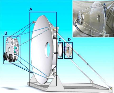
Figure 1. Schematic of the system: (A) 1.3 m primary mirror, (B) secondary mirror with dithering mechanism, (C) cryostat window lens, (D) detector focal plane module. For clarity, the cryostat is not shown. Inset is a photograph of the primary and secondary mirror assembly.
Millimeter-wave technology for application in security screening and imaging has been an area of intense research over the last few years because of the possibility to confer both acceptable spatial resolution (mm-level) and penetration of clothing and some packaging materials using non-ionizing radiation. There are both active and passive designs and the NIST Security Technologies Group (STG) has research projects related to both.
Passive 350 GHz Millimeter wave system for video rate standoff imaging
The STG, in collaboration with the NIST Quantum Electromagnetics Division, has developed a state-of-the-art passive millimeter-wave imaging system based on cryoelectronic sensor arrays. This system will be the basis for the development of NIST’s millimeter-wave imager metrology, including the development of test artifacts, test and evaluation protocols, and international documentary standards.
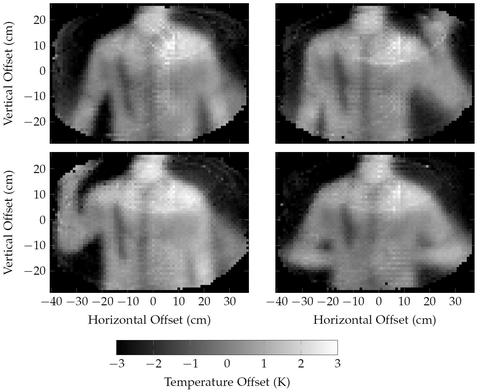
The system is designed to image stationary and non-stationary objects at video rates at a standoff distance of 10 m to 20 m. The system utilizes an f/2.0 Cassegrain optical system with a 1.3 m primary mirror (see figure 1). The light then passes into a cryostat and through a set of filters that define the 10% bandwidth, centered at 350 GHz. The focal plane is cooled to 950mK to facilitate the use of superconducting transition edge sensor (TES) bolometers. Figure 2 shows images from a video in which a weapon is concealed beneath a shirt.
- A 350-GHz high-resolution high-sensitivity passive video imaging system
- High-Resolution Passive Video-Rate Imaging at 350 GHz
- Standoff passive video imaging at 350 GHz with 251 superconducting detectors
VIDEO: “NIST Imaging System Detects Hidden Threats (link is external)”
Contacts
-
(301) 975-8821