
Official websites use .gov
A .gov website belongs to an official government organization in the United States.
Secure .gov websites use HTTPS
A lock (
) or https:// means you’ve safely connected to the .gov website. Share sensitive information only on official, secure websites.
Sample Experimental Thermal Storage Data
The Intelligent Building Agents Laboratory (IBAL) was constructed as a testbed to demonstrate the potential for distributed, intelligent software agents to automatically operate building HVAC systems to reduce energy consumption and operating costs. Details of the design of the laboratory and information about the sensors deployed in the lab can be found in the listed publications.
Charging the Thermal Storage Tank Data Set
- Experiments.zip (includes experimentTags1.JSON and experimentTags2.JSON)
- MetaData.csv
- ProcessData.csv
- RawData.csv
- ScaledData.csv
This data set contains the results from two days of operation. During those two days the thermal storage tank, an ice on coil design, was charged from 0 % to 100 % ice using the larger of the two chillers in the laboratory, Chiller 2. The experimentalTags.JSON file contains general information about the test. The MetaData.csv file contains information about all the sensors and control signals currently in use in the IBAL. Many of the sensors were not used in this test, but the most relevant measurements for this data set are listed in Table 1 and Table 2.
The ProcessData.csv file contains information about the controls, such as the chiller set point temperature and the PID gains and parameters used to set the temperature in the Condensing Loop. The RawData.csv and ScaledData.csv files contain the raw measurement data and the data scaled using the coefficients in the metadata file, where a0, a1, and a2 are the coefficients of the zeroth, first, and second order terms of a polynomial fit.
The chiller in this test has a capacity of 36 kW (10.25 tons) at design conditions and uses a scroll compressor with R410A. The working fluid in the system is 30 % propylene glycol. The chiller is water cooled using the Condensing Loop in the lab, which is supplied by chilled water from the campus that enters the lab at approximately 42 °F. The chiller set point is - 6.7 °C (20 °F). The specifications for the thermal storage tank are:
- 274 kWh (78 ton-hours)
- 3104 L (820 gallons)
- 1.873 m (73.75 in) diameter
- 2.08 m (82 in) high
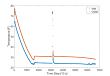
The data are collected at a 0.10 Hz rate. Figure 1 shows an example of how this data set can be used. Two of the most important measurements when charging an ice tank are the temperature of the propylene glycol entering and leaving the tank. This figure shows how those temperatures change as the ice making process proceeds. At first, the water in the tank is cooled down to below the freezing point of water, a process known as supercooling. Supercooling occurs when water is cooled but ice does not form due to a lack of nucleation sites. Once ice begins to form, the temperature increases as is seen around time step 1750. After that point the inlet and outlet temperatures slowly decrease, with the exception of the spike around time step 3200, which is the transition from the first to the second day of charging (i.e., the system was shut down in between these days). The charging process is complete when the outlet temperature reaches 28 °F.
Related Publications:
- Pertzborn, A., "Intelligent Building Agents Laboratory: Hydronic System Design," NIST Technical Note 1933, Gaithersburg, MD., September 2016.
- Pertzborn, A., "Measurement Uncertainty in the Hydronic System in the IBAL," NIST Technical Note 1970, Gaithersburg, MD., September 2017.
Related Programs/Projects:
The IBAL is part of the Embedded Intelligence in Buildings Program at NIST. This program includes the Automated Fault Detection and Diagnostics for the Mechanical Services in Commercial Buildings Project and the Smart Building Automation and Control Testbed and Standards Project.

The IBAL will produce a large set of data. Please let us know if you find the type of data published here useful or if you have suggestions for other types/formats of data that would be useful to you.
Contacts
-
(301) 975-5879
-
(301) 975-5873