Official websites use .gov
A .gov website belongs to an official government organization in the United States.
Secure .gov websites use HTTPS
A lock (
) or https:// means you’ve safely connected to the .gov website. Share sensitive information only on official, secure websites.
Additive Manufacturing with Cement-based Materials
Summary
Additive Manufacturing (AM) with concrete, also known as 3-D Concrete Printing (3DCP) and more recently Additive Construction (AC) with concrete, is an emerging and rapidly evolving technology in the construction industry. This approach to concrete construction has the potential to change the way cementitious materials are used to create infrastructure components. Automating the placement of concrete materials may improve construction efficiency by eliminating the need to erect formwork, improve infrastructure durability by providing precise control of concrete formulations, and improve construction safety by removing humans from hazardous working environments. Rapid construction enabled by 3DCP techniques can provide shelter to communities affected by natural disasters, build with local materials in hostile environments (e.g., military and mining applications), build taller wind turbine towers to access higher energy winds, and repair concrete in areas which are hard to access with conventional construction equipment. The concrete design and engineering community lacks sufficient knowledge about the performance of 3DCP structures subjected to designed loading scenarios to properly design 3DCP structures for a given application. The role of the printing process in determining the failure mode and a detailed understanding of the relationship between the 3DCP structure’s constituent material properties and structural response are critical to developing performance-based standards and guidelines for 3-D printing construction techniques. Developing this knowledge base and coupling it to measurements of concrete materials in the 3DCP process would mark a significant step toward revolutionizing concrete construction.
Description
Objective - Develop the measurement science tools and scientific knowledge base for performance-based standards for reinforced 3-D printed concrete structures.
Background - Current 3DCP construction practices resemble reinforced masonry construction, as shown in Figure 1. Similar to reinforced concrete masonry unit (CMU) construction, in 3DCP, reinforcing bars are grouted in various locations in the webbing or infill pattern. The performance of these structures subjected to loads anticipated by engineering designs and unanticipated, episodic loading has yet to be evaluated. Questions surrounding the effect of the 3DCP construction technique on performance and failure of the fabricated structure remains unknown. For instance, the interface between layers and the connection between the webbing and perimeter layers are likely to be pathways for crack propagation. Furthermore, the performance of 3DCP structures may be dependent on machine settings and material formulations. Developing and understanding of the link between material properties, machine settings, and structural performance is key to developing performance-based standards and guidance for 3DCP.
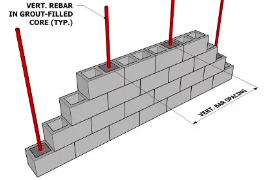
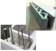
Figure 1: Reinforced 3DCP resembles reinforced masonry construction with CMU. (a) Schematic of reinforced masonry construction and (b) an implementation of similar reinforcement techniques in 3DCP.
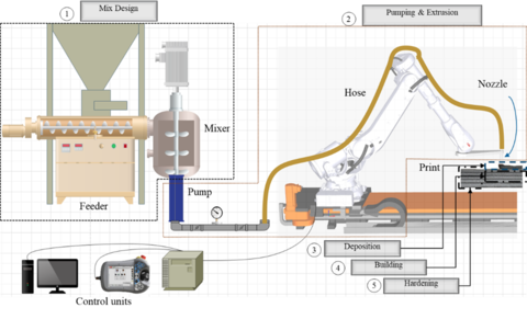
Concrete AC is a dynamic process. whereby the kinetics of chemical reactions (hydration) influence the rheology (flow). The hydration and rheology control properties such as the building rate, material strength and the bonding of one layer to the previous layer. This dynamic process occurs at multiple length and time scales. Nanoscale C-S-H (the calcium silicate hydrate that binds concrete together) formation affects macroscopic material properties related to rheology and compressive strength. The layer-by-layer deposition of material used in AC will require new standard practices and guidance for specifying/accepting material formulations and evaluating the performance of structures. New metrologies are needed to measure the complex rheological properties of AC materials during the construction process. Developing these in-situ rheology measurements could provide important feedback into the construction robot to eliminate manufacturing defects. In the hardened state, existing material and structural testing methods may not be applicable to this type of construction. The layered construction introduces anisotropy, and the layer interface bonding could provide a preferential pathway for crack propagation. The performance of AC materials and structures must be evaluated to determine if existing building codes and standards are suitable for evaluating structures fabricated by AM techniques. Successful implementation of concrete AC will require an understanding of how the underlying material properties are influenced by the process parameters (print speed, geometry, and orientation) which further influence the performance of AC infrastructure components. This is generally covered in three steps from mix design through extrusion and finally hardened or cured properties (Figure 2).