
Official websites use .gov
A .gov website belongs to an official government organization in the United States.
Secure .gov websites use HTTPS
A lock (
) or https:// means you’ve safely connected to the .gov website. Share sensitive information only on official, secure websites.
Problem
Pressure measurements still rely on external pressure transducers. The problem is one cannot accurately measure the local pressure in a microfluidic system due to the pressure dissipation and delay in transmission. The NIST Optical Flow Meter provides on-chip assessment of flow and heat transfer which enables improvement in fluid metrology AND paves the way for new opportunities in microscale calorimetry and biological sensing.
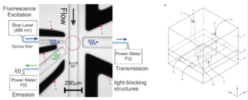
Invention
Optofluidics is the marriage of microfluidics and optical technology. The NIST Optical Flow Meter (US Patent 10,151,681) provides an on-chip assessment of flow and heat transfer, resulting in vast improvements in fluid metrology and advances in biological sensing.
Potential Commercial Applications
- Point of Care Diagnostics
- Flow Cytometry
- Cell Counting
- Live Cell Imaging
- Microfluidic Drug Administration at the Cellular Level
- Makes precise measurements of smaller quantities in real time
- New strategy to accurately determine measurement uncertainty near zero flow – useful for flow control and determination of fluidic conductance
Competitive Advantage
- Provides measurement of microscale forces pressure for a fluid-carrying article
- Placing pressure sensors into a microfluidic chip is the most accurate in situ pressure measurement
- Flow measurement at 10 nL/min with 5% uncertainty using dosage relationship to scale down existing flow calibration by approximately a factor of 10 (calibrated meter at 150 nL/min)
- Flow control to within 5 % uncertainty down to 1 nL/min
- Cost-effective and easy to use