
Official websites use .gov
A .gov website belongs to an official government organization in the United States.
Secure .gov websites use HTTPS
A lock (
) or https:// means you’ve safely connected to the .gov website. Share sensitive information only on official, secure websites.
Helping the Microchip Industry Go (Very Low) with the Flow
A new NIST analysis reveals a heated source of potentially expensive errors.
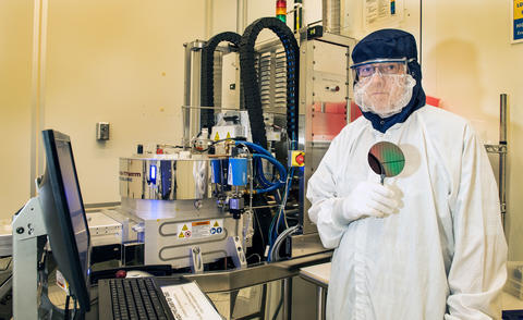
Process Engineer Richard Kasica of NIST’s Center for Nanoscale Science and Technology holds a wafer of the type typically produced in the plasma-enhanced chemical vapor deposition chamber at center.
A new study by scientists at the National Institute of Standards and Technology (NIST) has uncovered a source of error in an industry-standard calibration method that could lead microchip manufacturers to lose a million dollars or more in a single fabrication run. The problem is expected to become progressively more acute as chipmakers pack ever more features into ever smaller space.
The error occurs when measuring very small flows of exotic gas mixtures. Small gas flows occur during chemical vapor deposition (CVD), a process that occurs inside a vacuum chamber when ultra-rarefied gases flow across a silicon wafer to deposit a solid film. CVD is widely used to fabricate many kinds of high-performance microchips containing as many as several billion transistors. CVD builds up complex 3D structures by depositing successive layers of atoms or molecules; some layers are only a few atoms thick. A complementary process called plasma etching also uses small flows of exotic gases to produce tiny features on the surface of semiconducting materials by removing small amounts of silicon.
The exact amount of gas injected into the chamber is critically important to these processes and is regulated by a device called a mass flow controller (MFC). MFCs must be highly accurate to ensure that the deposited layers have the required dimensions. The potential impact is large because chips with incorrect layer depths must be discarded.
“Flow inaccuracies cause nonuniformities in critical features in wafers, directly causing yield reduction,” said Mohamed Saleem, Chief Technology Officer at Brooks Instrument, a U.S. company that manufactures MFCs among other precision measurement devices. “Factoring in the cost of running cleanrooms, the loss on a batch of wafers scrapped due to flow irregularities can run around $500,000 to $1,000,000. Add to that cost the process tool downtime required for troubleshooting, and it becomes prohibitively expensive.”
Modern nanofabrication facilities cost several billion dollars each, and it is generally not cost-effective for a company to constantly fine tune CVD and plasma etching. Instead, the facilities rely on accurate gas flows controlled by MFCs. Typically, MFCs are calibrated using the “rate of rise” (RoR) method, which makes a series of pressure and temperature measurements over time as gas fills a collection tank through the MFC.
“Concerns about the accuracy of that technique came to our attention recently when a major manufacturer of chip-fabrication equipment found that they were getting inconsistent results for flow rate from their instruments when they were calibrated on different RoR systems,” said John Wright of NIST’s Fluid Metrology Group, whose members conducted the error analysis.
Wright was particularly interested because for many years he had seen that RoR readings didn’t agree with results obtained with NIST’s “gold standard” pressure/volume/temperature/time system. He and colleagues developed a mathematical model of the RoR process and conducted detailed experiments. [https://www.nist.gov/publications/errors-rate-rise-gas-flow-measurements-flow-work] The conclusion: conventional RoR flow measurements can have significant errors because of erroneous temperature values. “The gas is heated by flow work as it is compressed in the collection tank, but that is not easily accounted for: it is difficult to measure the temperature of nearly stationary gas.”
Wright and colleagues found that without corrections for these temperature errors, RoR readings can be off by as much as 1 percent, and perhaps considerably more. That might not seem like a lot, but low uncertainty is critical to attaining uniformity and quality in the chip manufacturing process. And the challenge is growing. Current low-end flow rates in the semiconductor industry are in the range of one standard cubic centimeter (1 sccm)—about the volume of a sugar cube—per minute, but they will soon shrink by a factor of 10 to 0.1 sccm.
Precise flow measurement is a particularly serious concern for manufacturing processes that use etching of deposited layers to form trench-like features. In that case, the MFC is often open for no more than a few seconds.
“A tiny amount of variation in the flow rate has a profound effect on the etch rate and critical dimensions of the structures” in very large-scale integrated circuits, said Iqbal Shareef of Lam Research, a company headquartered in California that provides precision fabrication equipment to microchip manufacturers.
“So, we are extremely concerned about flow rates being accurate and consistent from chamber to chamber and wafer to wafer,” Shareef said. “Our industry is already headed toward very small flow rates.”
“We are talking about wafer uniformity today on the nanometer and even subnanometer scale,” Shareef said.
That’s very small. But it’s what the complexity of three-dimensional chip manufacturing increasingly demands. Not so long ago, “a 3D integrated circuit used to have four layers of metals,” said William White, Director of Advanced Technology at HORIBA Instruments Incorporated, a global firm that provides analytical and measurement systems. “Now companies are regularly going to 32 layers and sometimes to 64. Just this year I heard about 128.” And some of those chips have as many as 3,000 process steps.
“Each 300 mm wafer can cost up to $400, and contains 281 dies for a die size of 250 to 300 mm2,” Brooks’ Saleem said. “Each die in today’s high-end integrated circuits consists of about three to four billion transistors. Each wafer goes through 1 or 2 months of processing that includes multiple runs of separate individual processes,” including chemical vapor deposition, etch, lithography and ion implantation. All those processes use expensive chemicals and gases.
Many companies are already re-examining their practices in light of the NIST publication, which provides needed theoretical explanations for the source of RoR flow measurement errors. The theory guides designers of RoR collection tanks and demonstrates easy-to-apply correction methods. RoR theory shows that different temperature errors will occur for the different gases used in CVD processes. The NIST publication also provides a model uncertainty analysis that others can use to know what level of agreement to expect between MFCs calibrated on different RoR systems.
“NIST serves as a reliable reference for knowledge and measurement where industry can assess agreement between their systems,” Wright said. “As manufacturers’ measurement needs push to ever lower flows, so will NIST calibration standards.”
Note: Any mention or depiction of commercial products is for information only; it does not imply recommendation or endorsement by NIST.