
Official websites use .gov
A .gov website belongs to an official government organization in the United States.
Secure .gov websites use HTTPS
A lock (
) or https:// means you’ve safely connected to the .gov website. Share sensitive information only on official, secure websites.
Free Download
Overview
NIST has created a Test System to measure conformance of Computer-Aided Design (CAD) software to American Society of Mechanical Engineers (ASME) standards for Product and Manufacturing Information (PMI), specifically geometric dimensioning and tolerancing (GD&T) information.
PMI includes geometric dimensioning and tolerancing, 3D annotations, surface texture specifications, finish requirements, process notes, material specifications, welding symbols, and other information. One of the objectives of PMI standards is to define the semantics of the words and symbols used to communicate manufacturing information in 3D computer models. The use of PMI Representation (aka semantic PMI) will allow software developers to automate various design (CAD), manufacturing (CAM), and inspection (CMM) functions because the engineering application software associated with these functions can process the PMI directly. PMI presentation (aka graphical PMI) consists of geometric elements preserving the exact appearance of the PMI annotations and is meant to be human-readable.
All of the resulting test cases, CAD models, STEP files, and reports can be download through the link to the left. These files can be used to test Model-based Design (MBD) and Model-based Engineering (MBE) workflows.
Short URL: go.usa.gov/mGVm
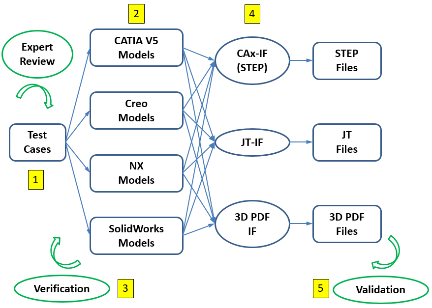
Test System Components
The test system has five main components:
- Test Case definition and expert review
- Test CAD Model creation based on the test case definition
- Verification of the CAD models against the test case definitions
- Generation of derivative STEP, JT, and 3D PDF files by the Implementor Forums
- Validation of the derivative files against the CAD models and test case definitions
Test Cases
A representative collection of PMI concepts commonly used in practice were selected from ASME Y14.5-1994 (Dimensioning and Tolerancing) and ASME Y14.41-2003 (Digital Product Definition Data Practices) from which a set of test cases were developed for determining whether CAD software correctly implements the PMI concepts. ASME Y14.5 defines the symbology used for specifying PMI. ASME 14.41 specifies how to present PMI in 2D and in 3D. The most current versions of ASME Y14.5 (2009) and Y14.41 (2012) are not included as they have not yet been widely implemented in CAD software.
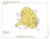
There are two types of Test Cases. Both types of test cases are 2D drawings of an annotated 3D model that is used as the basis for authoring the CAD test models.
Combined Test Case (CTC)
A Combined (or Complex) Test Case (CTC) is a combination of Atomic Test Cases (ATC). An Atomic Test Case highlights an individual PMI annotation to be tested, called the measurand. The ATC is not a complete specification of the part's PMI, but rather contains only the PMI needed to specify enough context information to understand the measurand. Typically this means one or more examples of the measurand, along with any datum features referenced. ATCs, although useful for conformance testing, are not "realistic" in that they include only measurand-related PMI.
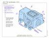
A Combined Test Case (CTC) is superset of the PMI of all ATCs for a particular part model. Each CTC specifies one of the five distinct part geometries developed for the project. Depending on the complexity of the part, its CTC may provide more than one view. A CTC is not intended to be a fully-toleranced test case, it is only a combination of PMI from a set of ATC.
Click on the thumbnails for the Test Case Drawings.

| 
| 
| 
| 
|
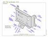
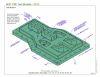
Fully-Toleranced Test Case (FTC)
An FTC is a Fully-Toleranced Test Case where the intent is to have all of the geometric features fully-toleranced in the context of GD&T. Fully-toleranced means that each tolerancing feature on a model is adequately controlled and constrained by tolerances that comply with the applicable dimensioning, tolerancing, and modeling standards. Each FTC includes as many annotation types and constructs needed to fully control and constrain each feature relative to one or more datum reference frames.

| 
| 
| 
| 
| 
|
Test Case Expert Review
The Test Cases were peer-reviewed by several GD&T experts to ensure that PMI concepts were correctly specified according to the ASME Y14 standards, that appropriate concepts were covered, and to minimize errors and misunderstandings. The Test Cases are not intended to represent best practice in how to apply GD&T to a part. Simpler GD&T strategies could have been used. The Test Cases are intended to exercise valid presentations of GD&T defined in the ASME Y14 standards.
Test CAD Models
Test Cases alone are insufficient for automated conformance testing to take place. For each Test Case, a Test Model generated in four CAD systems. Test models were generated from the geometrical definition and PMI concepts represented in the corresponding test case. As best as possible, the PMI concepts were modeled in the CAD system as semantic information rather than just graphical presentations. Issues in modeling PMI concepts in each CAD system were documented and shared with the CAD system software vendor to determine whether the issue was due to misuse of the CAD system to generate a particular PMI construct or truly resulted from a lack of capability of the CAD system.
The native CAD models have been tested in the CAx Implementor Forum (CAx-IF), JT Implementor Forum (JT-IF), and 3D PDF Implementor Forum.
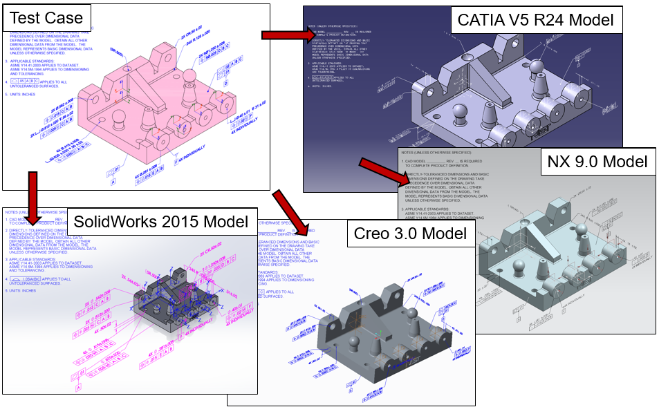
(The screenshots above do not necessarily reflect current capabilities of the CAD systems.)
CAD Model Verification and Derivative File Validation
A key objective of the project is to verify and validate the semantic representation of PMI concepts in CAD models. For model verification and validation, each of the native CAD models from one CAD system are compared to the equivalent native CAD models from the other CAD systems. This round-robin verification process serves to ensure that all of the native CAD models are as equivalent as possible to each other from a geometry and PMI standpoint. Feedback from the verification process is used to refine the CAD system test models. Verification categories include many characteristics of geometry and GD&T annotations.
The validation process compared derivative STEP, JT, and 3D PDF files to the original native CAD models. Feedback from the validation process is used to improve CAD system STEP, JT, and 3D PDF translator software.
Publications
- Testing Implementations of Geometric Dimensioning and Tolerancing in CAD Software
- Guide to the CAD Models and Verification Testing Results
- Measuring the PMI Modeling Capability in CAD Systems: Report 1 - Combined Test Case Verification
- Measuring the PMI Modeling Capability in CAD Systems: Report 2 - Combined Test Case Validation
- Measuring the PMI Modeling Capability in CAD Systems: Report 3 - Fully-Toleranced Test Case Verification