
Official websites use .gov
A .gov website belongs to an official government organization in the United States.
Secure .gov websites use HTTPS
A lock (
) or https:// means you’ve safely connected to the .gov website. Share sensitive information only on official, secure websites.
Summary
The NIST Neutron Imaging Facility (NNIF) at the NIST Center for Neutron Research.
Description
Available as a national user facility since 2006, the NIST Neutron Imaging Facility provides users with a unique “plug and play” approach to imaging operating fuel cells and electrolyzers. In 2016, the NIST-NeXT system was first installed, allowing simultaneous neutron/X-ray tomography of complex materials and systems such as batteries, concrete, shales, and two-phase flow in granular media. The neutron beam characteristics of the facility are detailed below.
Facility Neutron Optics
This facility (see Fig. 1) is located at Beam Tube 2 (BT-2) at the NIST Center for Neutron Research (NCNR). The NCNR provides an extremely intense source of thermal neutrons that is collimated using a tapered plug (1 and 2 in Fig. 2). This conically shaped beam is nearly uniform in intensity across the diameter of the beam at the image plane downstream. This type of optical arrangement is generally referred to as pinhole optics.
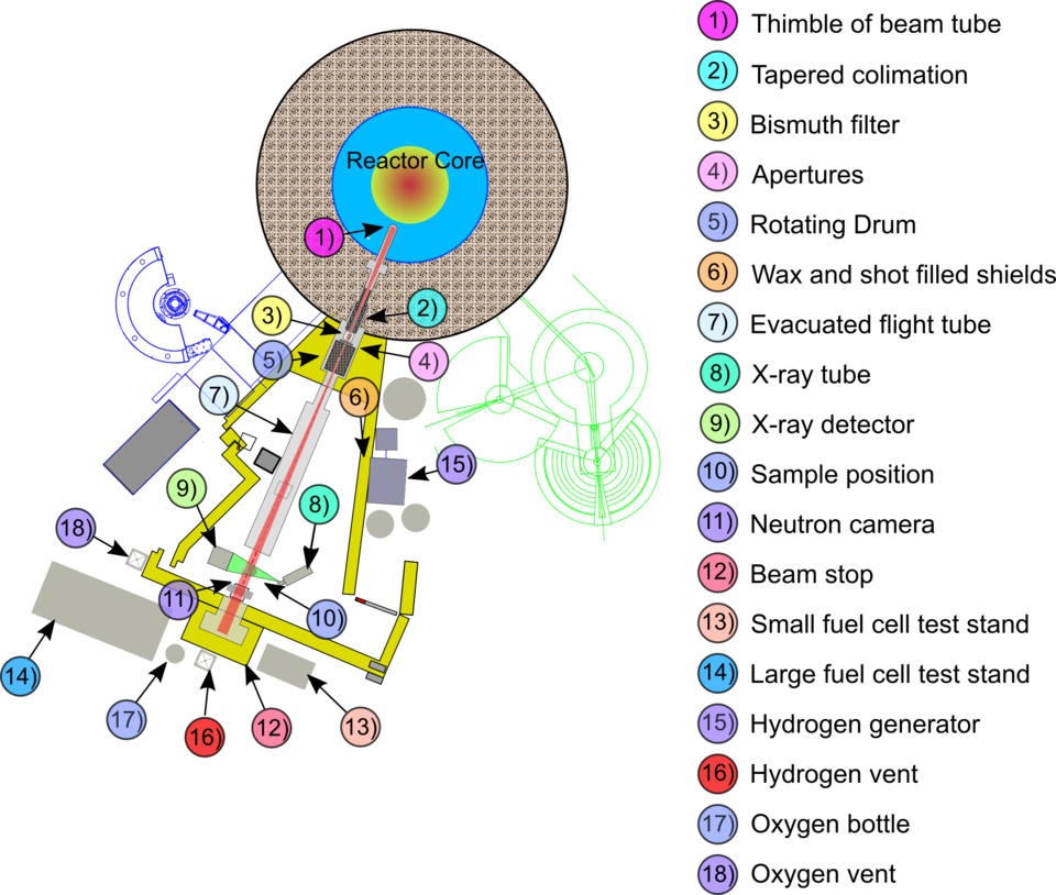
Although the NCNR produces mostly thermal neutrons, there is still a significant amount of high energy neutrons and gamma rays as a byproduct. These high energy neutrons and gamma rays represent a background that can be dangerous to electronic equipment and to personnel operating the beam line. Therefore, a high energy neutron and gamma ray filter is placed directly downstream of the tapered collimator. This filter consists of 10 cm of bismuth single crystal cooled to liquid nitrogen (LN) temperatures (77 K) (3 in Fig. 2). Cooling the bismuth dramatically reduces the vibrational phonon modes in the crystal, which strongly scatter thermal neutrons. Cooled the crystal becomes nearly transparent (60 % transmission) to thermal neutrons and remains nearly opaque to high energy neutrons and gamma rays.
The filtered beam can then be collimated with a simple thermal neutron pinhole located directly downstream of the LN cooled bismuth filter. The maximum diameter of this pinhole is 2 cm and the minimum size is unrestricted; however, the current system is setup to use a 2 cm, 1.5 cm, 1.0 cm, 0.5 cm, or 0.1 cm aperture. Using a 2 cm aperture produces an effective L/d ratio (to be discussed later) of 300. Smaller diameter apertures increase this ratio and enhance the resolution of images. The full range of parameters are shown in Table 1.
Table 1. General beam characteristics are described here. The last column shows the values for no filter for the sake of comparison to other neutron radiography facilities.
|
L (m) |
Aperture d (cm) |
L/d |
Beam diameter (cm) |
15 cm bismuth filter Fluence Rate (cm-2 s-1) |
No filter Fluence Rate (cm-2 s-1) |
|---|---|---|---|---|---|
|
2 |
2 |
100 |
8 |
5.1 × 10⁷ |
3.0 × 10⁸ |
|
3 |
2 |
150 |
13 |
3.4 × 10⁷ |
2.0 × 10⁸ |
|
4 |
2 |
200 |
17 |
2.5 × 10⁷ |
1.5 × 10⁸ |
|
6 |
2 |
300 |
26 |
1.7 × 10⁷ |
1.0 × 10⁸ |
|
6 |
1.5 |
400 |
26 |
1.0 × 10⁷ |
5.9 × 10⁷ |
|
6 |
1.0 |
600 |
26 |
4.3 × 10⁶ |
2.5 × 10⁷ |
|
6 |
0.5 |
1200 |
26 |
1.0 × 10⁶ |
5.9 × 10⁶ |
|
6 |
0.1 |
6000 |
26 |
4.3 × 10⁴ |
2.5 × 10⁵ |
After the pinhole is a rotating drum with four positions (4 in Fig. 2). Three of the positions have holes for additional collimation or filters if needed. These collimators are currently 1 cm, 2 cm, and open collimation. The fourth position is used to block the beam when the facility is not in use.
Neutrons and gamma rays scattered out of the beam must be stopped to prevent them from becoming a hazard to personnel or to other scientific neutron data collection experiments in the NCNR. The shielding used to do this is a steel encased mixture of wax and steel shot. The high energy neutrons are turned into thermal neutrons in the wax and stopped by the material and the gammas are absorbed by the steel shot (see 6 in Fig. 2).
The beam that is now collimated passes out of the drum and into a sealed, evacuated aluminum flight tube (7 in Fig. 2). The flight tube ends right before the sample position (10 in Fig. 2), which is open to air. At the sample position an object to be radiographed sits on a rotating and translating stage. Behind the object is the neutron camera that is used to digitize the 2-dimensional neutron distribution (11 in Fig. 2). An X-ray imaging system (8 and 9 in Fig. 2) sits perpendicular to the neutron beam at the sample position to allow simultaneous neutron and X-ray tomography.
Finally, the beam is stopped in an appropriately named "beam stop" (12 in Fig. 2). The beam stop is necessary since the sample and camera do not stop all of the neutrons plus high energy neutrons and gammas are still present in the beam. Therefore, for the interest of safety the beam stop is designed to stop the unattenuated beam (beam without obstructions like the sample and camera).
Additional infrastructure at the facility includes equipment to support fuel cell testing (13-18 in Fig. 2). Full details of equipment available at the instrument can be found on the facility infrastructure and equipment page.