
Official websites use .gov
A .gov website belongs to an official government organization in the United States.
Secure .gov websites use HTTPS
A lock (
) or https:// means you’ve safely connected to the .gov website. Share sensitive information only on official, secure websites.
A team of researchers at NIST's Antenna Metrology Lab in Boulder, CO has devised a first-of-its-kind system – combining a precision 3-meter industrial robot arm with a metrology-grade laser tracker and other apparatus – that can measure an antenna's performance from every point in a spherical area around it, determine its position to within 25 micrometers (RMS) while it is moving, and do it all repeatably.
The system, now undergoing testing and refinement will bring a new and much-needed dimension of accuracy to the task of characterizing and calibrating antennas for use at 50 GHz to 500 GHz. That range spans the most important frequencies used by Earth-observation satellites for climate studies, among other applications.
The higher frequencies are also in growing demand for current and future telecommunications and imaging applications. But "currently there are no international reference standards for antennas above 110 GHz," says team member David Novotny of the Radio-Frequency Fields Group in PML's Electromagnetics Division. "So there is no way to compare and validate measurements at different facilities. We hope to be able to measure probe antennas that are then used by others to characterize systems to a common baseline."
At present, the vast majority of such measurements are taken using planar systems in which the scanning stages for the probe antenna (which typically receives the signal) are often mounted on granite slabs for stability. The antenna under test (AUT) is then moved sequentially in two dimensions to different locations relative to the probe. As a practical matter, this method usually constrains scan angles to about 35 degrees of arc, which significantly limits the amount of information about the AUT that can be gathered.
More complete characterization requires a spherical scan that measures the AUT's performance from many different angles. That can be approximated by combining data from multiple planar geometries; but re-aligning the AUT and probe to a fraction of a wavelength is an expensive and laborious process that is unsuitable for frequencies above 100 GHz.
Instead, the PML team created a multi-component, multi-sensor dynamic system with a total of 12 degrees of freedom in orientation and alignment: six from the industrial robot arm and end unit that holds the probe antenna, and six from the separate robotic positioner that holds the AUT on its stage.
Laser beams reflecting off targets on the end of the arm track the probe position. Typically, the AUT transmitter is kept motionless on its stage while the probe antenna receiver sweeps through an arc of up to 240 degrees around it. Then the AUT is rotated by a small increment and another sweep is made. The process is repeated until the data build up a spherical picture of antenna performance.
A major advantage of the robot-arm system is that it takes data while the probe antenna is continuously moving at a constant speed. "It's a dynamic measurement," says team member Joshua Gordon. "If you were to start and stop the arm for each measurement, it would shake the structure and it would take a lot of time for that vibration to dissipate. We avoid that problem, and we've been able to get high repeatability and to position the probe to within 50 micrometers, and track the probe within 25 micrometers."
The ability to measure positions accurately also allows for antennas to be measured off axis. This will be helpful when measuring antenna systems such as those used in satellites where alignment fiducials may not necessarily be centered on the radiating aperture.
25 micrometers – about one-fourth the width of a human hair – might seem to be a reasonably small uncertainty. But "your allowable error is proportional to the wavelength," says team member Jason Coder. At 500 GHz (wavelength ~ 0.6 mm), it will be necessary to know the probe position to within 15 to 20 micrometers and to ensure that the probe is normal to the scan surface within 0.05 degrees. Moreover, a truly comprehensive characterization will require not only measurements of the exact relative distance and angle between the antennas, but also the relative alignment of their apertures.
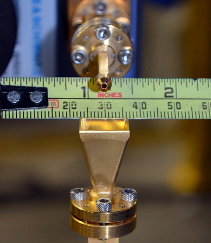
Since the probe aperture is only about 1 mm wide, and the longest horn dimension is ~13 mm (see image below) that is a significant challenge. To address it, Gordon is developing new techniques for measuring these delicate antennas at a distance of several centimeters without having to physically touch them. Once the specific details of alignment are identified and quantified, the result can be fed into an algorithm that adjusts the entire data-set by applying the correction globally.
At present, there are two principal applications for the robot-arm/laser tracker system. One is in the nation's evolving telecommunications systems, which will soon have to expand into higher frequencies as available spectrum at conventional frequencies become saturated.
A more immediate use is in calibrating the antennas used in satellite Earth-observation measurements. "Most remote observations from space are done with microwaves," says James Whetstone, who heads NIST's Greenhouse Gas and Climate Science Measurement program. "So improving the fundamental microwave metrology will ultimately hasten advances in remote sensing. Higher-frequency microwave observing systems will evolve, and this work will further that progress."
Detailed characterization of antennas may also improve resolution of key variables such as the 183 GHz water vapor signal. "Better spatial resolution at the surface and in the near atmosphere can provide essential information on the disposition and movement of water – notably drinkable water – on the surface," Whetstone says.
Understanding satellite antennas in detail, he says, can also minimize another potential source of error: side lobes in the antenna's radiation pattern. "For satellite observation work, the spherical measurements tell you a lot of important information that you simply can't get with planar scanning, such as the behavior of side lobes. Say your spacecraft itself is radiating at certain frequencies similar to the signal. If there is a side lobe to the pattern, energy can enter that way and distort your measurements."
The robot-arm/laser tracker system is particularly well suited to instrument clusters for orbiting satellites. "Often the chief item of interest isn't the antenna and its circuitry per se, but how multiple systems perform in concert," Coder says, "and we can accommodate a much larger test payload than a single antenna. With the new facility, if a customer was interested, we could put the entire small satellite -- up to 2 meters in diameter -- in here and characterize the system as a whole, which would be a huge advantage."
"It really helps that we can now align the probes without physically touching them," Novotny says. "We're often asked to characterize a device, but not allowed to touch it."
There may be other possible applications as well. The Journal of the CMSC (Coordinate Metrology Systems Conference), which is devoted to all kinds of 3-D measurement, featured the PML team's work in its Autumn, 2013 issue. Each year only the top eight papers from the CMSC conferences are granted publication in the Journal of the CMSC. "We were encouraged by that," Gordon says, "because it suggests that our system may be of interest to people in very different fields."
That seems likely. "No other national metrology institute is using robotics for dynamic measurements of this kind," says Perry Wilson, Leader of the Radio-Frequency Fields Group. "No other NMI is doing dynamic correction of position and orientation, much less alignment. It may seem hard to believe, but alignment is the biggest source of uncertainty in antenna measurements.
"But I think what's going to come out of this effort is not just a unique, state of the art antenna range. We're really going to progress into the whole area of using robotic technology for microwave metrology. And's that's something that has applications well beyond antenna patterns."