
Official websites use .gov
A .gov website belongs to an official government organization in the United States.
Secure .gov websites use HTTPS
A lock (
) or https:// means you’ve safely connected to the .gov website. Share sensitive information only on official, secure websites.
Helping Laser Scanners Measure Up
New method for rapidly providing highly calibrated standards
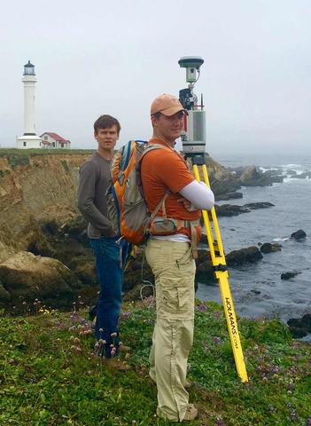
USGS student interns using a terrestrial laser scanner and GPS to map the elevation and deformation patterns of marine terraces along the northern California coast.
Scientists at the National Institute of Standards and Technology (NIST) have devised a novel, accurate, easy-to-operate, time- and labor-saving way to provide calibrated scale-bar standards for testing the performance of terrestrial laser scanner (TLS) systems.
TLS technology is widely employed to create detailed, high-resolution, 3D digital images of terrain, buildings, vegetation, construction projects, crime-scene forensics and – increasingly – very large objects such as airframe components that must be fitted together with precision, often on the scale of a few hundred micrometers (millionths of a meter; a human hair is about 100 micrometers thick).
“Of course, for geodesy and surveying and most forensic uses, you don’t really need micrometer resolution,” said NIST project scientist Vincent Lee. “But TLS systems are now often used in aerospace and ship building, where big components have to be joined very meticulously, like a wing onto a fuselage. That’s where measurements from a few hundred micrometers to a millimeter really matter.” And that’s where careful system testing really matters. [See Video 3 below.]
Many TLS systems operate like radar. Radar systems send out microwave beams and detect the distances to, and the shapes of, their targets by measuring the amount of time it takes for the beam to strike the target and bounce back to a detector – the longer the time, the greater the distance.
TLS uses pulsed laser light instead of microwaves. Some TLS systems are designed to collect hundreds of thousands of position data points (or more) per second and deliver measurements accurate to a few millimeters at a range of 100 meters.
Of course, that’s possible only if the systems have been adequately tested, a process that involves determining how precisely they can measure calibrated reference objects of exactly known dimensions. International consensus protocols (i.e., ASTM E3125-17) call for multiple length tests, which are typically made using a reference scale bar about 15 cm wide and 2.3 meters (about 7.5 feet) long. [See Video 1 above]
Mounted on each end and in the center of the bar are three targets: medium matte gray aluminum spheres, the centers of which are placed at presumably exactly known distances from one another during manufacturing. Calibrating a scale bar so that it can serve as a standard entails measuring and verifying those distances.
One familiar method requires the manufacturer to drill small holes through both sides of each sphere, aligned such that all the holes are precisely colinear. As a result, a single narrow laser beam from a device called a laser tracker is projected through the holes from one end of the bar, travels to the other end, strikes a special mirror called a retroreflector, and returns to exit the first hole and enter the detector in the laser tracker. The measurement is repeated to measure the distance between each of the targets. [See video 2 below.]
That is called the line-of-sight (LOS) method, and it currently serves as the de facto preferred technique. Since the speed of light is a precisely known fixed constant, the round-trip time is a highly sensitive measure of distance.
“But when one company sent us a scale bar, we found the LOS process to be very, very challenging,” said NIST guest researcher and Associate Professor at China Jiliang University, Ling Wang, part of the team that reports its findings in the February 2020 issue of Measurement. “We had some difficulty getting the beam perfectly aligned through those little holes and then thought about how somebody was going to do this in the field. So we said, ‘Let’s come up with an alternate way that’s easier for the user’.” The new method eliminates the need to drill holes in the targets and enables precision measurements with the laser tracker set up a couple of meters from the scale bar.
Because the targets are rigidly attached to the scale bar, and the bar is inflexible, the main source of uncertainty in measuring scale-bar dimensions is the “ranging” accuracy of the laser tracker. A single set of measurements from a fixed location and orientation might include errors resulting from tiny misalignments of the tracker components and/or irregularities in the “encoders” that process horizontal and vertical angle information.
To minimize those sources of uncertainty, the NIST team decided to take distance measurements of the target centers from four different tracker orientations: the first straight on, and then three more sets as the tracker was rotated by 90-degree increments relative to the scale bar. (See video.) The researchers hypothesized that averaging measurements from all the orientation would produce a reading with minimal errors.
The last tracker’s beam can also rotate 360 degrees vertically, and the team took measurements of the target positions with the beam source/detector (called the “front face”) right-side up, and the same measurements with the “back face” upside down. Again, averaging the measurements eliminated errors.
The scientists also made careful measurements of the target dimensions using the LOS technique. When they were compared to measurements using the new “four-orientation, two face” method, the difference was no more than a few micrometers, too small to have practical significance. And “it can be done in 15 or 20 minutes, versus one or two hours – or more— using the very inconvenient LOS method,” said NIST scientist Bala Muralikrishnan.
“NIST scientists who support dimensional metrology needs of U.S. advanced manufacturing are meeting the demands of industry to provide methods and techniques that give more information and capabilities to the users in the field and at the point of manufacture,” said Daniel Sawyer, leader of NIST’s Dimensional Metrology Group. “This new development meets this critical industrial need enabling the use of laser scanning instruments that will solve emerging measurement challenges in large-scale advanced manufacturing.”
Like many successful NIST efforts to improve metrology for commercial uses, the project benefitted from an industry partner – in this case, Bal-tec Industries, which provided a three-sphere scale bar for the research.
“This joint effort resulted in a new easier method to calibrate scale bars, creating a way for TLS users to more quickly and conveniently evaluate their measurement systems. Whether in a laboratory or out in the field, this method works in accordance with published standards such as the ASTM E3125-17,” said article co-author Joseph Gleason, Director of Engineering at ScanningSpheres, a division of Bal-tec.
Paper: L. Wang, B. Muralikrishnan, V. Lee, P. Rachakonda, D. Sawyer and J. Gleason. Methods to calibrate a three-sphere scale bar for laser scanner performance evaluation per the ASTM E3125-17. Measurement. Published February 2020. DOI: https://doi.org/10.1016/j.measurement.2019.107274
Disclaimer: Any depiction or mention of commercial products within NIST web pages is for information only. It does not imply recommendation or endorsement by NIST, nor does it imply that the materials or equipment identified are necessarily the best available for the purpose.