
Official websites use .gov
A .gov website belongs to an official government organization in the United States.
Secure .gov websites use HTTPS
A lock (
) or https:// means you’ve safely connected to the .gov website. Share sensitive information only on official, secure websites.
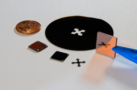
Samples of various materials tested in the NIST study. Clockwise from the penny: a silicon wafer with its center cut out, gallium phosphide, silicon (cross), germanium, and zinc telluride.
Semiconductors are the cornerstone of modern electronics. They’re used in solar cells, light emitting diodes (LEDs), microprocessors in laptops and cell phones, and more. Most of them are made of silicon, but silicon has its limitations. So for decades researchers have been exploring new materials with properties that make them good candidates for better, lighter, and cheaper energy-efficient lamps, solar cells, and even – someday, perhaps – solar energy-harnessing “paint.”
To decide whether a new material has promise as a semiconductor or meets a manufacturer’s specifications, companies need to be able to essentially count the number of freely moving “charge carriers” floating within the material, as well as their mobility or how easily they are able to move. Negative carriers are electrons; positive carriers are referred to as “holes” and are places where an electron is missing. Semiconductors are typically doped with impurities to increase the number of free electrons in one area of the material and the number of free holes in another area of the material, which gives the semiconductor a negative and positive side.
The traditional way of measuring charge carrier concentration, called the Hall method,* takes some time and skill: it requires hand-soldering a series of metal electrical contacts onto a wafer of the material, exposing that wafer to a magnetic field, applying a current, and measuring a voltage. (See animation.)
But while the Hall method works well for silicon, it often doesn’t work at all for many promising exotic materials. “The contacts don’t adhere,” says Ted Heilweil of the NIST Physical Measurement Laboratory (PML). “You just can’t get the stuff to stick.”
Heilweil and his NIST colleagues have been exploring another potential option, a method that doesn’t require any electrical contacts at all. Instead, it involves shining pulses of light through a sample of the semiconductor material and measuring the amount that comes out the other side.
The new laser-based method gauges the number of charge carriers in the material using terahertz (THz) radiation, which has a wavelength much longer than the human eye can see, in the far infrared to microwave range. To THz light, pure silicon and other semiconductors are essentially invisible. But one thing that absorbs that light is freely moving charge carriers. So the more free electrons and holes there are in the material, the less light shines through.
To see how well the newer method measures up against the traditional Hall technique, the NIST team performed both tests on a wide range of sample wafers and crystals, all commercially available and under active study by industry. The samples included both pure silicon wafers and silicon wafers doped with various impurities, as well as pieces of germanium and crystals of zinc telluride, gallium arsenide, and gallium phosphide. The sample thicknesses ranged from 300 micrometers to only 4 or 7 micrometers – a fraction of the thickness of a human hair.
NIST PML’s Robert Thurber, who has spent decades measuring wafers using the traditional method, tested each sample using the Hall technique. He then passed those samples to Heilweil’s lab for testing with the terahertz apparatus. NIST National Research Council (NRC) postdoctoral researcher Brian Alberding also worked to perform and analyze the optical measurements.
The result? The optical method works well, Heilweil says. For the silicon wafers, the numbers from the Hall and THz methods were in good agreement – within 50% of each other – and also generally matched what has been published by other labs in the past. For the non-silicon samples where both types of measurement could be done, the values were also in good agreement, falling within one another’s measurement uncertainties. This success gives the researchers more confidence in the THz measurements they made on materials (such as zinc telluride) that cannot be reliably tested using the Hall method.
The study represents the first time, to the authors’ knowledge, that the new and old methods have been used on the same samples. “It always bothered me that there was a contact method and a non-contact method, but there was no comparison between the two,” Heilweil says. “Using this approach, we were able to make very good comparisons.”
A bonus for this method is that it can be used to study photo-doping, or the use of light to temporarily increase a semiconductor’s conductivity. This is basically how a solar cell works: the Sun illuminates a material and an equal number of electrons and holes are generated. For this work, the NIST researchers activated the material using a second beam of light with a different frequency, dependent on the material being probed. They then used the terahertz beam to tell them how many free electrons and holes were generated, as well as their mobility, or how easily they can move through the material.
In addition to allowing the assessment of materials that could not be tested before, the laser technique could be used for quicker quality-control work for silicon wafers. Someday, testing could be as easy as inserting a sample into an optical reader and getting a result almost immediately. This is potentially great for research and development, Heilweil says, because companies could quickly test new ideas, devices, and materials to see how well they are working.
For now, though, the technique requires an expensive laser system, so it would need to be commercialized before it could be integrated into most manufacturers’ laboratories. Meanwhile, Heilweil continues using the laser method to study exotic materials such as ruthenium oxide, a promising transparent conducting material, as well as graphene and other conductive 2D materials with nanoscale layers, which could one day be used to paint electronics onto surfaces. “I think if I can make a little bit of a dent in the scientific community in that way it would be very cool,” Heilweil says.
-- Reported and written by Jennifer Lauren Lee
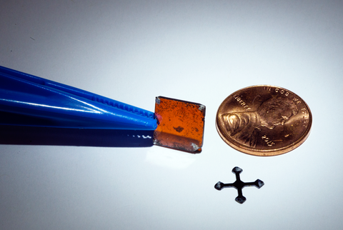
* The Hall method measures the number of charge carriers in a material – related to the material’s conductivity. First, current is made to flow diagonally across a material sample, typically shaped like a square or cross (see photo above). Next, the material is exposed to a magnetic field whose orientation is 90 degrees relative to the direction of the current. The magnetic field causes more free electrons or holes to pool up on one side of the material relative to the other. This difference in number of electrons or holes produces a voltage across the material, measured through the other two corners of the sample. Resistance is the ratio of voltage to current, and conductivity is the reciprocal of resistivity (related to resistance).
For information about the Hall Effect on which this measurement is based, see The Hall Effect.