
Official websites use .gov
A .gov website belongs to an official government organization in the United States.
Secure .gov websites use HTTPS
A lock (
) or https:// means you’ve safely connected to the .gov website. Share sensitive information only on official, secure websites.
Principles of Neutron Stress Measurements
Diffraction methods, regardless of the type of radiation used (election beam, X-ray, or neutrons) measure distances between ordered arrangements of atoms or, more precisely, between lattice planes in crystalline materials. Most materials are crystalline in structure; the differences are mostly in the size of the constituent crystals (also called grains). Interatomic distances change linearly with stress up to maximum values of several 10-3 in relative terms at the so-called yield stress. Higher stresses cause plastic (permanent) deformation where, similar to spreading a deck of cards, slip occurs along atomic planes while the distance between planes stays the same. Continued slip often causes hardening and it increases the yield stress.
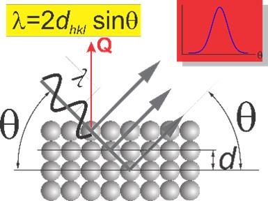
Thermal neutrons have two key properties that enable the spatially resolved measurement of stress: 1) low absorption in most engineering materials allowing penetrations of several millimeters to centimeters, and 2) wavelengths l suitable for diffraction at angles at 2q»90° where spatial resolution is optimal.
Aperture systems for the incident and diffracted neutron beams define the gage volume for which volume-averaged lattice spacings d are measured through Bragg’s law. The measured lattice spacing are subject to changes induced by stresses present at a given location in the sample. The orientation of the sample is critical for discerning the directionality of the stresses (stress tensor).
During a measurement the neutron optical components remain unchanged; only the sample moves, either by translation or rotation. This way it is possible to accurately measure relative changes in d-spacings caused by stresses.
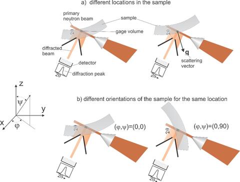
Tri-axial stresses are determined from different locations in the sample and different orientations of the sample. Using the stress-free lattice spacing d0 strains are obtained from which stresses are calculated through the generalized Hooke’s law. The value d0 can be measured on small coupons or calculated from balance conditions.
Strictly speaking, it is not necessary to define a gage volume for a measurement of applied stress if two conditions are met: a) stresses within the illuminated volume are homogeneous, and b) the sample remains stationary within the scattering plane.
Contacts
-
(301) 975-5380