
Official websites use .gov
A .gov website belongs to an official government organization in the United States.
Secure .gov websites use HTTPS
A lock (
) or https:// means you’ve safely connected to the .gov website. Share sensitive information only on official, secure websites.
Millimeter-Wave Channel Sounding and Modeling
Work groups within IEEE, 3GPP, and other standards developing organizations are currently scrambling to define new specifications for the design and planning of millimeter-wave (mmWave) systems. All the while, there is consensus throughout the wireless community that existing channel models in this frequency regime are either unreliable – often retrofitted from sub 6-GHz legacy models with mmWave measurements – or insufficient – propagation is not fully understood despite significant efforts, especially in the past three years, to characterize the channel. Apart from the open literature, we know of commercial stakeholders such as equipment manufacturers and service providers who have taken measurements to generate their own models. Due to the expense involved, their results are held proprietary and for internal consumption only; in the best case, they are discussed to a limited degree in closed standardization fora. Through measurement campaigns with our own custom state-of-the-art channel sounders, the aim of this project is to furnish the wireless research community with advanced mmWave propagation models to help stakeholders bring finalized products to market as efficiently as possible.
Channel Sounding
Switched-Array Channel Sounders
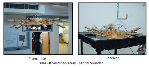
We have designed and assembled switched-array channel sounders at 28-, 60-, and 83-GHz. The 60-GHz sounder is shown below. The transmitter (TX) is mounted on a tripod and the untethered receiver on a mobile robot. The robot’s laser-guided navigational system generates a 2D map of the environment and reports its position on the map. The robot’s speed and heading are also reported. The receiver (RX) features a circular array of 16 horn antennas, each with 18.1 dBi gain and 22.5° beamwidth. To avoid “blind spots,” the elements are arranged such that the angular offset between them is matched to beamwidth of the horns so that the RX field-of-view (FOV) is omnidirectional in azimuth. The 3D arrangement enables characterizing angle in both azimuth and elevation. The TX array is a replica of the RX array. The angle-of-arrival of each path is determined by comparing its delay across the RX-array elements: as the plane wave approaches the array, its arrival angle will be closest (farthest) to the boresight angle of the element that detects the path first (last). Based on this principle, any angle in between can be interpolated by finding the relative delay between the elements for which the pulses combine coherently in amplitude. The principle is the same for the angle-of-departure at the TX array. The azimuth and elevation of the AoD and AoA were validated with a mean error of 2.1 °
Virtual-Array Channel Sounders
To report channel parameters with greater precision, we transferred the RX-array mount from the robot onto a 2D positioner. The positioner sequentially translates the switched-array antenna structure across a regularly spaced grid of 30 x 30 points through mechanical scanning in the horizontal plane. Because our RX array has 16 horn antennas, the system is equivalent to 16 synthetic planar arrays, each with a FOV corresponding to a single horn, but that collectively has the same omnidirectional FOV of the switched-array system. However, there are three important advantages:
- The points are spaced at half-wavelength, so coherent combination in complex amplitude – incorporating phase to deliver high resolution – is possible. Accordingly, the inherent 22.5° beamwidth of the horns is collapsed to a 3.8° pencilbeam that can be steered in any direction within the FOV. This means that even paths arriving within the same delay bin can be resolved in angle;
- The 18.1 dBi gain of the horns multiplied by the directivity of the array factor – 29.5 dBi at boresight – provides for a peak synthetic-array gain of 47.6 dBi, yielding a maximum measureable path loss of 192 dB to deal with comparable mmWave loss expected;
- Each point of the synthetic array is digitized separately, enabling the use of advanced super-resolution techniques.
Phased-Array Channel Sounders
While our synthetic-array channel sounder enables a very high degree of precision in parameter estimation, it is very slow: a channel sweep requires 44 minutes and so only static environments can be characterized. To meld the speed of the switched-array system with the precision of gridded elements, our next generation of channel sounders implements real phased-array antennas. The figure below shows our 60-GHz phased-array channel sounder. While slower than the switched array, it is steerable and its beamwidth is tunable, with nominal 3.6 ° beamwidth and 28-dBi gain. Each board can scan 90 ° in azimuth and so to enable an omni view, the boards are arranged at right angles at both the RX and TX. The beam pattern can be switched at a rate of 30 MHz, so a full RX-TX sweep requires only 0.33 s. We have a similar phased array at 28GHz that has separate feeds for both polarizations.

Channel Modeling
The precise calibration and verification methods for mmWave systems enable us to develop accurate channel propagation models for our field measurements, the main thrust of the project. We have made significant progress in characterizing path-loss models, map-based dispersion models, Doppler frequency-spread models, multipath tracking, and human blockage. Some details follow.
Quasi-Deterministic Channel Model
The IEEE 802.11ay task group as well as other industry consortia have subscribed to map-based channel models for mmWave systems, of which the Quasi-Deterministic (QD) model has become the benchmark. In the QD model, the direct path and reflected paths only are considered as diffraction has been demonstrated to be much weaker in mmWave bands. The direct path is completely deterministic: its geometrical properties (delay, angle-of-arrival, angle-of-departure) are computed from the TX and RX coordinates and its path loss from Friis transmission equation in LOS. Specular reflections are also deterministic: their geometrical properties are computed from raytracing (provided a map of the environment in addition to the TX and RX coordinates) and their path loss is the sum of the free-space loss plus any reflection loss. Each specular reflection gives rise to scattering of the incident wave into a dominant specular multipath and weaker diffuse components clustered around the cursor. The stochastic property of the model concerns the small-scale statistics of the clustered scattering. We compute QD parameters such as the reflection loss of the cursors and the angular spread of the clusters from measurements. A MATLAB implementation of the model can be found here: https://github.com/usnistgov/qd-realization
Multipath Tracking
The figure on the left visualizes multipath tracking across 108 RX positions in a lecture room using our 60-GHz switched-array system. The TX is labeled on the map of the environment while the ground-truth (reported from robot) RX positions are marked with Xs. The dominant paths were tracked on the map: the direct path was estimated as the position of the RX while the reflected paths from the ceiling, tables, right wall, and top wall – each marked with a different symbol according to the legend – were estimated as the location of their reflection points. Each symbol is color-coded against path gain. For the direct path and right-wall reflections, the paths were detected for all RX positions while for the other three, only segments were detected. Accordingly, the beginning and end positions for each path were labeled. The three waypoints where the robot turned (positions 51, 70, and 95) are also labeled for reference.
Human Blockage
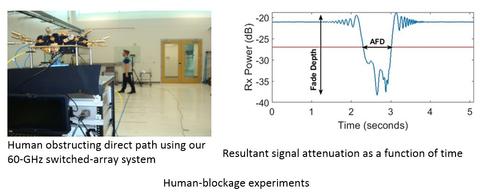
Device-to-Device (D2D) models at mmWave will suffer from blockage from humans, vehicles, etc. given the low base-station height. From our observations (figure below), as well as many others, the slow fading (shadowing) of human blockage will range between 20 – 25 dB. While significant, the signal may still be recoverable for data transmission depending on the link budget. That is why – while the vast majority of papers only report on the slow fading – fast-fading characteristics of the blocked signal are also important, yet still lacking in literature. This is the subject of our current analysis.
Outdoor Measurements
We have equipped our mobile robot with ruggedized wheels so that we can conduct measurement campaigns outdoors. We have expended significant effort in getting our location services operational outdoors via precision differential GPS, which delivers good long-term accuracy, coupled with an Inertial Measurement Unit (IMU), which delivers more stable short-terms accuracy, especially for heading, but suffers from long-term drift. Because the heading serves as a reference for our angle estimation, we fuse the GPS and IMU through Kalman filtering to deliver sub-degree heading error. We are also currently in the process of procuring a GSA van for high-speed vehicular measurements. We have collected data in downtown Boulder and other measurements slated for the upcoming year are in urban-canyon Denver and at Union Station. In the grand scheme of things, our intention is to extend the indoor models we have developed for path loss, dispersion, Doppler frequency, and multipath tracking to outdoors.
5G mmWave Channel Alliance
There is an industry- and research-community need for accurately characterizing the mmWave bands beyond 6 GHz. While there are many groups currently working on 5G channel measurements and modeling (METIS2020, COST1004, 5G Channel Model SIG, IEEE 802.11adNG60, ETSI mmWave SIG, NYU Wireless), many of these efforts are focused on developing channel models for specific wireless systems and may be short-lived or adapted once initial standards are put in place. In response to this need, NIST founded the 5G mmWave Channel Model Alliance of companies, academia, and government organizations to allow rapid development of more accurate, consistent, and predictive channel models. The Alliance hosted a kick-off meeting in July 2015. Since then, the Alliance has grown to a total of 139 members. The Alliance has continued to build momentum – over the past 6 months in particular – and thus far can show for the following:
- Measurement white paper:
The purpose of this paper is to develop methods for comparing different channel sounders, each with differences in filtering, scaling, and other post-processing techniques. We explain cutting-edge calibration, verification, and measurement techniques specific to mmWave channel sounders. The 111-page complete document is currently authored by 25 experts from 13 different organizations worldwide and is ready for submission for book publication together with the modeling white paper (below).
- Modeling white paper:
The purpose of this paper is to provide cutting-edge modeling techniques specific to mmWave wireless systems. The document has grown to 168 pages authored by 18 experts from 12 different organizations worldwide.
- Measurement and model repository:
The website (https://5gmm.nist.gov/) was launched in December 2016 and serves as a repository for contributions of measurement data and models for mmWave channels. By aggregating data in multiple environments across multiple frequency bands, data can be compared, contrasted, and validated; in addition, the data can be used for modeling research for institutions that do not have the resources to collect data on their own. Thus far we have a total of 53 data-set submissions from five different organizations.
- Workshops:
The Alliance has hosted three workshops thus far: the first was in December 2016 in association with IEEE Globecom conference and the second in September 2017 in association with the IEEE VTC-Spring conference. The next conference will be held in August 2018, again associated with the IEEE VTC-Spring conference
A new item for FY19 will be to deliver our first channel model, for the urban-canyon environment at 28-GHz center frequency. Thus far, we have formed a subgroup of seven institutions (USC, NCSU, Ilmenau TU, NYU Wireless, Durham University, and NIST), each with outdoor channel sounders in this frequency band. The channel model will be derived from measurements collected in different cities by the different entities and, as such, will be have broad representation.
We also expect many more Alliance members to contribute data and models to the repository. Finally, we expect to continue to host one or two workshops per year.
References
Publications:
- P.B. Papazian, K.A. Remley, C. Gentile, and N. Golmie, “Radio channel sounders for modeling mobile communications at 28 GHz, 60 GHz, and 83 GHz,” IEEE Global Symposium on Millimeter Waves, May 2015. http://ieeexplore.ieee.org/document/7175448/
- P.B. Papazian, J.-K. Choi, J. Senic, P. Jeavons, C. Gentile, N. Golmie, R. Sun, D. Novotny, K.A. Remley, “Calibration of Millimeter-wave Channel Sounders for Super-resolution Multipath Component Extraction,” IEEE European Conf. on Antennas and Propagation, April 2016. http://ieeexplore.ieee.org/document/7481704/
- P.B. Papazian, C. Gentile, K.A. Remley, J. Senic, and N. Golmie, “A Radio Channel Sounder for Mobile Millimeter-Wave Communications: System Implementation and Measurement Assessment,” IEEE Transactions on Microwave Theory and Techniques, vol. 64, no. 9., pp. 2924-2932, Sept. 2016. http://ieeexplore.ieee.org/document/7534832/
- C. Gentile, J. Senic, P.B. Papazian, J.-K. Choi, and K.A. Remley, “Pathloss Models for Indoor Hotspot Deployment at 83.5 GHz,” IEEE Global Communications Conference, December 2016. http://ieeexplore.ieee.org/document/7848995/
- R. Sun, P.B. Papazian, J. Senic, Y. Lo, J.-K. Choi, K.A. Remley, C. Gentile, “Design and Calibration of a Double-directional 60 GHz Channel Sounder for Multipath Component Tracking,” IEEE European Conf. on Antennas and Propagation (BEST PAPER AWARD), March 2017. http://ieeexplore.ieee.org/document/7928270/
- J. Wang, C. Gentile, P.B. Papazian, J.K. Choi, and J. Senic, “Quasi-Deterministic Model for Doppler Spread in Millimeter-Wave Communication Systems,” IEEE Antennas and Wireless Propagation Letters, vol. 16, pp. 2195-2198, May 2017. http://ieeexplore.ieee.org/document/7931542/
- K.A. Remley, J.A. Gordon, D. Novotny, A.E. Curtin, C.L. Holloway, M.T. Simons, R.D. Horansky, M.S. Allman, D. Senic, M. Becker, J.A. Jargon, P.D. Hale, D.F. Williams, A. Feldman, J. Cheron, R. Chamberlin, C. Gentile, J. Senic, R. Sun, P.B. Papazian, J. Quimby, M. Mujumdar, N. Golmie, “Measurement Challenges for 5G and Beyond: An Update from the National Institute of Standards and Technology,” IEEE Microwave Magazine, vol. 18, no. 5, pp. 41-56, July 2017. http://ieeexplore.ieee.org/document/7942230/
- J. Wang, C. Gentile, J. Senic, R. Sun, P. Papazian, and C. Lai, “Unsupervised Clustering for Millimeter-Wave Channel Propagation Modeling,” IEEE Vehicular Technology Conf. – Fall, Sept. 2017. https://ieeexplore.ieee.org/document/8288377/
- K.A. Remley, C. Gentile, A. Zajic, J. Quimby, “NIST Methods for Channel Sounder Measurement Verification,” IEEE Vehicular Technology Conference – Fall, September 2017. https://ieeexplore.ieee.org/document/8288374/
- J. Senic, C. Gentile, P.B. Papazian, J.-K. Choi, K.A. Remley, and J.-K. Choi, “An Analysis of Millimeter-wave Pathloss and Propagation Mechanisms in the Indoor Environment,” IEEE Transactions on Antennas and Propagation, vol. 65, no. 12, pp. 6562-6573, Dec. 2017. http://ieeexplore.ieee.org/document/7967756/
- J. Wang, C. Gentile, P.B. Papazian, J.K. Choi, and J. Senic, “Quasi-Deterministic Model for Doppler Spread in Millimeter-wave Communication Systems,” IEEE Antennas and Wireless Propagation Letters, vol. 16, pp. 2195 - 2198, May 2017. https://ieeexplore.ieee.org/document/8319437/
- R. Sun, P.B. Papazian, J. Senic, C. Gentile, K.A. Remley, “Angle- and Delay-Dispersion Characteristics in a Hallway and Lobby at 60 GHz,” IEEE European Conf. on Antennas and Propagation, 2018. https://ieeexplore.ieee.org/document/8288374/
- C. Lai, R. Sun, C. Gentile, P.B. Papazian, J. Wang, J. Senic, “Methodology for Multipath-Tracking in Millimeter-Wave Channel Modeling,” IEEE Trans. on Antennas and Propagation, March 2019. https://ieeexplore.ieee.org/document/8581503/
- C. Gentile, P.B. Papazian, N. Golmie, K.A. Remley, P. Vouras, J. Senic, J. Wang, D. Caudill, C. Lai, R. Sun, J. Chuang, “Millimeter-Wave Channel Measurement and Modeling: A NIST Perspective,” IEEE Communications Magazine, vol. 56:12, pp. 30-37, Dec. 2018. https://ieeexplore.ieee.org/document/8570037/
- R. Sun, C. Gentile, J. Senic, P. Vouras, P.B. Papazian, N. Golmie, K.A. Remley, “Millimeter-Wave Propagation Channels vs. Synthetic Beamwidth,” IEEE Communications Magazine, vol. 56:12, pp. 53-59, Dec. 2018. https://ieeexplore.ieee.org/document/8570040/
- P.F. Wilson, K.A. Remley, W.F. Young, C. Gentile, J. Ladbury, D.F, Williams, “A NIST Perspective on Metrology and EMC challenges for 5G and Beyond,” IEEE Electromagnetic Compatibility Magazine, vol. 7:4, pp. 77-85, 2018. https://ieeexplore.ieee.org/document/8637299/
Standards Contributions:
- A. Malstev,…, C. Gentile, P. Papazian, J.-K. Choi, J. Senic, J. Wang, D. Lai, N. Golmie, K. Remley, et al., “Channel Models for IEEE 802.11ay,” Document IEEE 802.11-15/1150r9, March 2017. https://mentor.ieee.org/802.11/dcn/15/11-15-1150-09-00ay-channel-models-for-ieee-802-11ay.docx
- P. Papazian, K. Remley, C. Gentile, N. Golmie, “NIST Millimeter-wave Channel Sounders” Document IEEE 802.11-15/342-ng60, March 2015. https://mentor.ieee.org/802.11/dcn/15/11-15-0342-00-ng60-nist-millimeter-wave-channel-sounders.pptx
- P. Papazian, K. Remley, C. Gentile, N. Golmie, J. Senic, J. Wang, and J.-K. Choi, “NIST Preliminary Channel Measurements at 83 GHz,” Document IEEE 802.11-15/840-ay, July 2015. https://mentor.ieee.org/802.11/dcn/15/11-15-0840-01-00ay-nist-preliminary-channel-measurements-at-83-ghz.pptx
- P. Papazian, K. Remley, C. Gentile, N. Golmie, J. Senic, J. Wang, and J.-K. Choi,“Preliminary Q-D Model for Lab Environment at 83 GHz,” Document IEEE 802.11-15/1283-ay, Nov. 2015. https://mentor.ieee.org/802.11/dcn/15/11-15-1283-00-00ay-preliminary-q-d-model-for-lab-environment-at-83-ghz.pptx
- A. Malstev, P. Papazian, K. Remley, C. Gentile, N. Golmie, J. Wang, and J.-K. Choi, J. Senic, “NIST Channel Model for Conference Room at 83 GHz,” Document IEEE 802.11-16/338-ay, March 2016. https://mentor.ieee.org/802.11/dcn/16/11-16-0338-00-00ay-nist-channel-model-for-conference-room-at-83-ghz.pptx
- D. Lai, J. Wang, C. Gentile, P. Papazian, J.-K. Choi, J. Senic, N. Golmie, K. Remley, “Multipath Component Tracking and Channel Model for Lecture Room,” Document IEEE 802.11-16/846-ay, July 2016. https://mentor.ieee.org/802.11/dcn/16/11-16-0846-00-00ay-multipath-component-tracking-and-channel-model-for-lecture-room.pptx
- P. Papazian, J.-K. Choi, R. Sun, J. Wang, J. Senic, C. Gentile, Y. Lo, K. Remley, “Quasi-Deterministic Channel Model for a Server Room at 60 GHz,” Document IEEE 802.11-16/1432r1-ay, Nov. 2016. https://mentor.ieee.org/802.11/dcn/17/11-17-0268-01-00ay-quasi-deterministic-model-for-doppler-spread.pptx
- C. Gentile, J. Wang, P.B. Papazian, J.-K. Choi, J. Senic, “Quasi-Deterministic Model for Doppler Spread,” Document IEEE 802.11-17/268r1-ay, March 2017. https://mentor.ieee.org/802.11/dcn/16/11-16-1432-01-00ay-a-quasi-deterministic-channel-model-for-a-server-room-at-60-ghz.pptx