Official websites use .gov
A .gov website belongs to an official government organization in the United States.
Secure .gov websites use HTTPS
A lock (
) or https:// means you’ve safely connected to the .gov website. Share sensitive information only on official, secure websites.
Temperature Sensitivity of Liquid Flow Meters
Summary
Currently it is desirable to calibrate mass flow meters in water at room temperature and use the meters to measure cryogens such as liquified natural gas (LNG). The objective of this project is to characterize temperature effects on mass flowmeters and provide a physical model that can predict behavior from measuring the resonance frequency of the flow tube(s) and using literature values for the temperature dependence of Young’s modulus and Poisson’s ratio.
Description
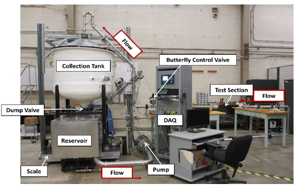
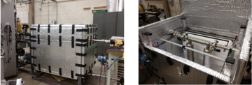
The Fluid Metrology Group is using NIST’s 15 kg/s water flow standard (Fig. 1) to test how coriolis meters are affected by liquid and environment temperatures. The water flow standard is a closed-loop, dynamic liquid flow calibration facility that is fully automated. For this work, calibrations were performed in the water flow facility at temperatures between 285 K and 318 K. The major components of the LFS include: 1) the flow generation and control system consisting of a variable flow pump, reservoir tank, check standard (or reference) flowmeter, butterfly valve, and data acquisition system with digital proportional-integral-derivative (PID) controller; 2) a test section that accommodates a meter under test with pipe diameter ranging from 1.25 cm to 5 cm; and 3) the dynamic weighing system comprised of a collection tank and weigh scale.
Major Accomplishments
-
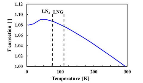
Fig. 2: Temperature correction factor for a coriolis meter. Credit: NISTNIST has developed a physical model based on Young’s modulus and Poisson’s ratio to hypothesize a correction factor for how coriolis will behave down to cryogenic temperatures. Figure 2 shows the meter correction factor that should be applied to Coriolis metes as a function of temperature.
- As a first step, we tested our model over the narrow liquid temperature range of 285 K to 318 K. The temperature dependence predicted by the model agrees with experimental data within ± 0.08 %; the model uncertainty is 0.16 % (95 % confidence level) over this temperature range.
- Published results in peer reviewed journal - Modeling temperature effects on a Coriolis mass flowmeter
- We postulate if shear modulus (in the form of Poisson’s ratio) is neglected, the Coriolis meter would have reported mass flow errors as large as 0.24 % in this small temperature range. We predict errors as large as 1.3 % and 1.6 % when measuring LNG at 111 K and LN2 at 77 K, respectively.