
Official websites use .gov
A .gov website belongs to an official government organization in the United States.
Secure .gov websites use HTTPS
A lock (
) or https:// means you’ve safely connected to the .gov website. Share sensitive information only on official, secure websites.
Summary
Radiometric, radiance temperature, photometric, and color scales have been realized based on the spectral responsivity of standard detectors and radiometers. These reference responsivity scales have been transferred to other NIST calibration facilities to realize and maintain these detector-based scales and decrease calibration and measurement uncertainties.
Description
Radiometric, radiance temperature, photometric, and color scales have been realized based on the spectral responsivity of standard detectors and radiometers. These reference responsivity scales have been transferred to other NIST calibration facilities to realize and maintain these detector-based scales and decrease calibration and measurement uncertainties.
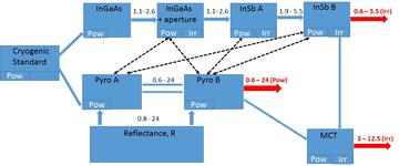
Multiple upgrades of the NIST IR calibration facility have made it possible to calibrate the spectral responsivity of detectors in the range of 0.6 µm to 24 µm in radiant power mode, and from 0.6 µm to 12.5 µm in irradiance mode. The available radiometric scale is supported by a set of the primary transfer radiometers (standards) currently used for both detector calibration and verification of the radiometric scale. The top standard is a cryogenic radiometer calibrated at few laser wavelengths. The radiant power scale from this standard is transferred to the sphere input extended-InGaAs radiometer, two InSb radiometers and two temperature stabilized pyroelectric radiometers. The continuous responsivity scale over the range 0.6 µm to 24 µm for the radiance power mode is realized by using the reflectance data of the pyroelectric detectors and a mutual scale correlation for all five radiometers in the spectrally overlapped regions. The latter procedure is also used for the periodical checkup of different standards assuming that their ageing effects would unlikely be the identical. Based on the observed agreement of measured responsivities, the spectral responsivity scale is maintained with an uncertainty of about 1%. The responsivity scale for the irradiance responsivity mode originates from the extended-InGaAs radiometer calibrated in the radiant power mode. This radiometer has a precise area aperture at the sphere input. Thus the irradiance responsivity RIRR may be found as RIRR = RPOW .S, where S is a known aperture area. The uncertainty of the scale in the irradiance mode is also about 1 % over the range of 0.6 µm to 5.2 µm. The extension of the scale to 12.5 µm by means of a large area MCT detector is currently in progress and the current uncertainty of its responsivity scale is about 3 %.
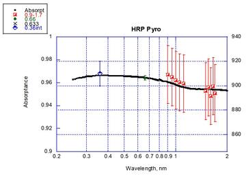
UV-VIS irradiance responsivity scale from broadband radiometric measurements. Low-NEP pyroelectric detectors with spectrally constant response extends the responsivity scale to 250 nm with an uncertainty of 0.3 % (k=2). The relative spectral responsivity of the pyroelectric detector known from spectral reflectance measurements is converted into spectral irradiance responsivity. The spectral responsivity was calibrated with a Si reference trap-detector and a 660 nm LED source. The flatness of the measured response function allows then the pyroelectric detector to be used as a standard for the broadband (integrated) irradiance measurements from UV and VIS LEDs.
Calibration facility and service
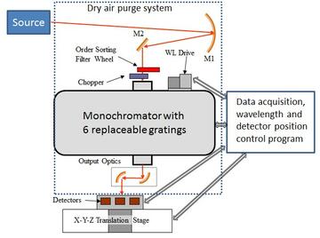
The facility designated for calibration of detector responsivity has two basic components: a source of radiation at the wavelength of interest and a standard detector with a known responsivity utilized as a reference for the detector to be calibrated. While a single wavelength source may be of particular interest, calibration over a wide spectral range provides valuable information for broadband applications of the detector. The NIST IRSCF presented here utilizes a broad band radiation source (1100 oC blackbody) and a monochromator-based system acting as a spectrally tunable bandpass filter. An f/4 monochromator operating with six diffraction gratings and a set of the order sorting filters, splits the entire operating range from 0.6 µm to 24 µm into a few smaller ranges to maximize the throughput of the IR radiation from the source. Fast access to the desired spectral sub-range is provided by a 4-grating turret in the monochromator. The optical system for delivery of the source radiation to the monochromator and detectors consists of a set of gold-coated mirrors. A compact and convenient configuration for the power responsivity mode consists of a 152 mm diameter f/2 spherical mirror at the input, and two 90o off axis parabolic mirrors at the output of the monochromator. In radiant power mode, the detector input beam is formed by two off-axis parabolic mirrors following the monochromator exit aperture. The two mirrors have different focal lengths in order to reduce the image size of the beam at the detector. The resulting beam diameter (full width half maximum) is about 2.4 mm and its profile is close to a Gaussian shape. The resulting geometry of the beam defines the diameter of the detector acceptable for calibration.
Since 2014, NIST offers the calibration service, special tests of customer-supplied ambient temperature infrared detectors in the 1.4 µm to 14 µm wavelength range or in extended range of 0.6 µm to 24 µm for certain detectors. The special tests include spectral power and/or irradiance responsivity and noise equivalent power measurements. The responsivity is calibrated in the units of V/W or V.W-1.cm2 in AC measurement mode at a chopping frequency of 10.5 Hz. The detectors to be tested should have a minimum sensor diameter of 5 mm (2 mm for irradiance mode) and acceptance angle of 20 degrees and include the preamplifier used with that detector. Accounting a big variety of infrared detectors, customers should contact Vyacheslav Podobedov (vyacheslav.podobedov [at] nist.gov (vyacheslav[dot]podobedov[at]nist[dot]gov)) to discuss details before submitting a formal request.
| Wavelength Range [µm] | Δλ | X, Y, Z Set Position | Output Ratio | Standard | Combined Uncertainty | Expanded Uncertainty (k = 2) |
|---|---|---|---|---|---|---|
| <1.4 | 0.07 | 0.5 | 0.07 | 1 | 1.1 | 2.2 |
| 1.4 - 3.5 | 0.09 | 0.5 | 0.04 | 1 | 1.1 | 2.2 |
| 3.5 - 6.5 | 0.09 | 0.5 | 0.04 | 1 | 1.1 | 2.2 |
| 6.5 - 14 | 0.05 | 0.5 | 0.22 | 1 | 1.1 | 2.3 |
| >14 | 0.08 | 0.5 | 0.5 | 1 | 1.2 | 2.5 |
| Wave-length range [µm] | Δλ | Distance | Field Non-uniformity | Output Ratio | Standard | Combined Uncertainty | Expanded Uncertainty (k = 2) |
|---|---|---|---|---|---|---|---|
| 0.6 - 5.3 | 0.09 | 0.8 | 0.3 | 0.1 | 1 | 1.3 | 2.6 |
| 5.3 - 12.5 | 0.08 | 0.6 | 0.8 | 0.5 | 1 | 1.5 | 3.0 |
IR detectors and radiometers
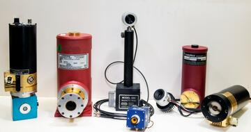

IR responsivity standards, from left to right: extended InGsAs sphere input-, cryogenic InSb-, temperature monitored pyroelectric-, room-temperature MCT-, temperature-controlled pyroelectric, cryogenic MCT- and InGaAs detectors
Sphere-input extended InGaAs standard has been developed to calibrate detectors and radiometers for absolute spectral power and irradiance responsivities between 0.95 µm and 2.5 µm. It includes an integrating sphere with 5 mm diameter input apertures mounted to the front of the sphere. Radiometer was calibrated at SIRCUS, the primary NIST reference for absolute responsivity.
Pyroelectric detectors are widely used for the detection of IR electromagnetic radiation. In contrast to their relatively low spectral responsivity and high NEP, the spectral range is extremely large, ranging from the UV to the IR. Most of the pyroelectric detectors tested until recently have had an NEP on the order of a few nW. After numerous iterative improvements, the most recent of these devices have exhibited a signal-to-noise performance about 200 times better than previously obtainable. Certain improvements in the pre-amplifier’s input electronic circuit, including an increase of the load resistor from 10 GΩ to 100 GΩ and optimization of the band pass (upper roll-off frequency), made it possible to significantly reduce the NEP of the pyroelectric detector. The noise measurements performed indicate the NEP of the advanced pyroelectric detector about 3.5.10-10 W Hz-0.5. A new type of hybrid temperature-stabilized pyroelectric detectors serves as primary calibration standard at the IRSCF.