
Official websites use .gov
A .gov website belongs to an official government organization in the United States.
Secure .gov websites use HTTPS
A lock (
) or https:// means you’ve safely connected to the .gov website. Share sensitive information only on official, secure websites.
Mercury Thermometer Alternatives: Verification Methods for Alternative Thermometers
Part of the process of ensuring that a thermometer is giving an accurate value -- and maintaining traceability -- is to verify the instrument's performance with respect to standards requirements.
Even the best instruments may give readings that are in error. Typical causes of erroneous readings include large mechanical shocks, large thermal shock, drift in the sensor or readout characteristics with time, or incorrect entry of calibration coefficients.
There are many methods for verifying that a thermometer is performing as intended, e.g., within manufacturer specifications or application uncertainty, described below. (There is also a video introduction to the subject.)
Digital thermometers
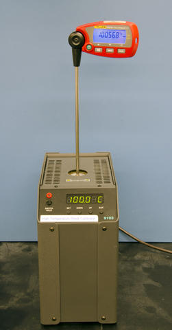
If the digital thermometer is used over a narrow temperature range (e.g., –50 °C to 100 °C), a single-point check at the ice melting point (0 °C) or at an ambient temperature is a sufficient method of performance verification. For temperature measurements above 100 °C, NIST's Temperature and Humidity Group (THG) recommends checking the thermometer at the steam point (e.g. ~100 °C), in addition to the ice melting point. If the device is used over a broader range (e.g., –196 °C to 500 °C), THG recommends combining the ice melting point with inspection of historical calibration records and periodic recalibrations to determine if the thermometers are drifting.
Organic-Liquid-Filled Glass Thermometers
These thermometers require visual inspection of the liquid column for breaks in the column if the thermometer has been shipped, stored horizontally, or cooled rapidly. If used in the range 0 °C to 50 °C (32 °F to 122 °F), a check at the ice melting point or at ambient temperature will suffice for verification. If used over a broader range, THG recommends combining inspection of historical calibration records with a check at 0 °C (32 °F) or at ambient temperature.
Four Methods for Thermometer Verification
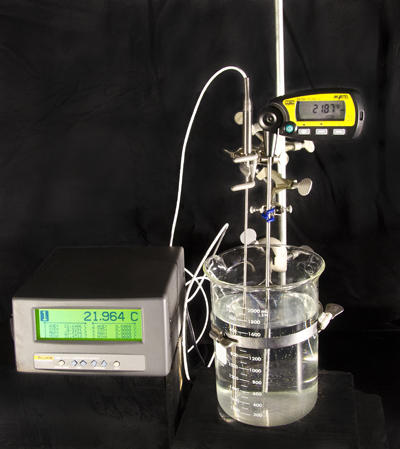
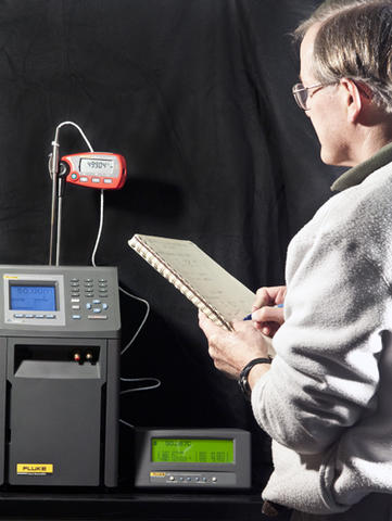
Comparison with another calibrated thermometer at ambient temperature
For this measurement, you need to have another calibrated thermometer. You also will need a glass beaker or large cup, tap water at room temperature, a magnetic stir bar and a magnetic stirring plate, or a hot plate with a stirring option. If you use the hot plate, do not energize the heated plate.
The measurement is straightforward:
- Fill the beaker or cup so that the water is at least 20 cm (approximately 8 in.) deep.
- Let the water sit for 2 hours (or ideally, overnight) so that the water temperature is nearly the same as the room temperature.
- Put the stir bar in the bottom of the beaker, place on the stir plate, and adjust to give a slow stir rate. The stir bar should revolve at about one revolution per second. (You can get good results stirring the liquid with a long rod instead of the stir bar, but you must be careful not to strike a sensitive thermometer probe with the long rod!)
- Insert the calibrated and test thermometers so that the tips of the probes are 10 cm to 15 cm (approximately 4 in. to 6 in.) below the surface of the water. (If a thermometer probe is very short, immerse the probe as deeply as you can without getting water in the wiring.)
- Wait 5 min.
- Record the readings of the thermometer you are testing, and then the calibrated thermometer.
- Repeat Step 5 and Step 6, but this time record the calibrated thermometer first, and then the test thermometer.
- If the calibrated thermometer has a correction to apply, make this correction according to the calibration certificate for the results of both Step 5 and Step 6.
- For both Step 5 and Step 6, subtract the corrected reading of the calibrated thermometer from the reading of the test thermometer. The result gives the error of the test thermometer.
- The measured error from Steps 5 and 6 should agree to within the repeatability of the thermometer. If not, try repeating the series of measurements, beginning at Step 4.
The picture on the right shows what the apparatus looks like.
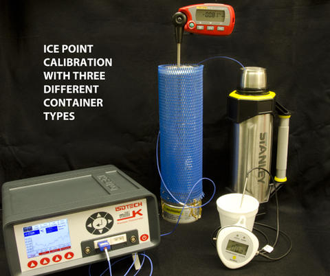
Measurement at the ice melting point (0 °C)
When ice and water are packed together into an insulated container, the mixture has a temperature of nearly 0 °C (32 °F). This mixture is the ice melting point. Important steps in preparing an ice point are:
- Use water that is distilled, de-ionized, or purified by reverse osmosis for both the water and the ice.
- The ice pieces should be no bigger than a gumdrop—about 1 cm or 0.5 in.
- Pack the container (e.g., insulated flask or Styrofoam cup) so that there is an ice-water mixture from top to bottom.
- When inserting the thermometer, make sure that it is clean, that it is immersed at least 10 cm to 15 cm (approximately 4 in. to 6 in.) (if possible), and that the probe tip is at least 2 cm (approximately 1 inch) from the container and about 5 cm (approximately 2 in.) from the bottom of the container.
The test thermometer should read 0 °C (32 °F). Any difference from these values is the measured error.
A NIST video gives all of the details in making an ice melting point that has an uncertainty (at 95 % confidence) of 0.01 °C (0.02 °F).
If you have access to distilled water and an ice crusher, you can actually achieve an uncertainty of 0.002 °C (0.004 °F). See Reference 1 from NIST for more details on how to make this type of ice melting point.
Measurement at the steam point (100 °C)
The steam point is not as commonly used as the ice point, but it provides a good method to verify thermometers at a second temperature. In this method, you create steam by boiling water in a beaker. As the steam rises, it will condense on a thermometer that is colder than the boiling point of the water. This condensation will raise the temperature of the thermometer until it is the same as the water boiling point. (There is an explanatory video of the procedure.)
The water boiling point, however, is NOT necessarily 100 °C (212 °F)! You need to correct the boiling point temperature for the elevation where you will do the measurement and for the barometric pressure. Luckily, you can readily look up elevation and barometric pressure data on the internet. To perform the calculations, you can download a steam-point calculator (Metric, English).*
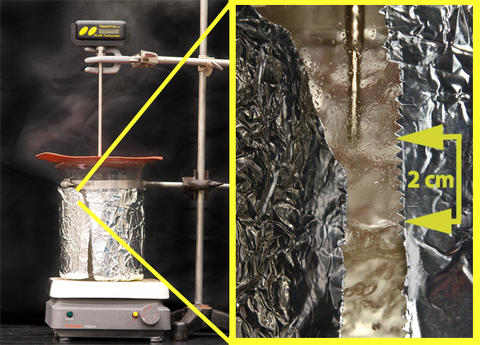
To do the measurement, you will need a hot plate, a stainless-steel beaker (or a glass beaker wrapped with aluminum foil on the outer side) at least 20 cm (approximately 8 in.) deep, a clamp to hold the test thermometer in place, and a silicone-rubber sheet to cover the beaker.
Here are some important points:
- The method uses boiling water and generates hot steam! Protect yourself from burns and scalding!
- Because evaporating water leaves behind any salts, the method may be used with simple tap water.
- The beaker should be filled with at least 4 cm (1.5 in.) of water. If a glass beaker is used, wrapping the outside cylinder with aluminum foil of the beaker (see photo below) helps prevent an error due to radiative cooling of the thermometer.
- A loose-fitting cover on top of the beaker ensures that steam fills the space below the cover. You can cut a disc with scissors from a silicone-rubber baking sheet, leaving a hole in the middle for the thermometer.
- Heat the water to a rolling, but not violent, boil.
- Use a clamp to hold the thermometer probe above the water, in the steam. The thermometer probe should not contact the boiling water.
- The thermometer probe should be immersed at least 10 cm to 15 cm (approximately 4 in. to 6 in.) into the space where steam collects.
- Wait 5 min. and record the reading of the thermometer.
- While you are waiting, you can use the calculator to find out the temperature of the steam point. Due to fluctuations in the barometric pressure, the steam point temperature may vary during the day.
The test thermometer should read the temperature calculated for the steam point. The test thermometer reading minus the calculated steam point reading equals the thermometer error.
* The correction for the elevation of the steam point above sea level is quite large For example, an altimeter pressure of 1013 hPa (29.92 in. Hg) will give a steam point temperature of 99.87 °C (211.77 °F), 99.46 °C (211.03 °F), 98.95 °C (210.11 °F), 97.94 °C (208.29 °F) and 94.89 °C (202.80 °F) for elevations of 30.5 m (100 ft), 152.4 m (500 ft), 304.8 m (1000 ft), 609.6 m (2000 ft), and 1524 m (5000 ft), respectively.
The uncertainty of the elevation limits the uncertainty of the steam point. Using the steam-point calculator, you can achieve an uncertainty of 0.1 °C (0.2 °F) at a 95 % confidence level.
Inspection of Historical Records
One weakness of the method is that the method gives no direct indication that a particular thermometer is performing correctly at the present time. On the other hand, for users who have many thermometers, or a long calibration history of one thermometer, this method gives a good statistical measure of the reliability of a thermometer. This method works best in combination with one or two of the other methods mentioned above.
To perform this method, the thermometer must be calibrated periodically, and for each calibration the readings of the thermometer must be recorded at the calibration temperatures with the instrument in the "as found" state. The user then calculates the difference between the "as found" readings with the results of the most recent prior calibration. This difference is the drift of the thermometer.
The drift should be determined for several different calibration temperatures, and for several different individual thermometers or for several calibration cycles of a single thermometer. The magnitude of the observed drift gives the user an indication of the typical drift to be expected for that thermometer (or thermometer type) in routine service. This can be plotted as a graph of changes over time.
What Do You Do If a Thermometer Fails Its Verification?
- First, check the instrument to see that you are using it correctly.
- Is the right probe connected to the readout?
- Are options for the readout set correctly?
- Do the batteries need replacing?
Repeat the verification measurement to confirm the first measurement.
If the results still show an error greater than the manufacturer specification or your application accuracy (tolerance), the instrument should be removed from service and recalibrated. Do NOT correct the reading by the observed error, unless the thermometer manufacturer recommends that you do so. Large errors may indicate that the instrument needs repair.
If a certain type of thermometer displays more than occasional verification failures, you may need to change either the procedure for handling the thermometer or the type of thermometer you use.
Any mention or image of commercial products within NIST web pages is for information only; it does not imply recommendation or endorsement by NIST.
Contacts
-
Questions about Mercury Thermometer Alternatives?