
Official websites use .gov
A .gov website belongs to an official government organization in the United States.
Secure .gov websites use HTTPS
A lock (
) or https:// means you’ve safely connected to the .gov website. Share sensitive information only on official, secure websites.
HFBS Instrument Details
The Backscattering Technique
Backscattering spectroscopy is based on the fact that the wavelength spread, δλ, of a Bragg-diffracted neutron beam decreases as the scattering angle, 2Θ, approaches 180°. The equation below, derived by differentiating Bragg's law and then dividing the result by λ, shows the dependence of the relative wavelength spread on the crystal planes and the scattering angle:
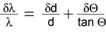
As Θ approaches 90°, the angular term vanishes. There is thus a minimum in the attainable wavelength spread that depends on the average value and spread of the spacing, d, between the Bragg planes in the crystal. The δd/d for the silicon (111) plane, the most commonly used configuration in backscattering instruments, is 1.86 x 10⁻⁵.
In the case of the HFBS, we have the following:
| Nominal neutron wavelength, λo | 6.271 Å |
| Corresponding wavevector, ko = 2π/λo | 1.00 Å-1 |
| Neutron speed | 630.8 m/s |
| Neutron energy | 2.08 meV |
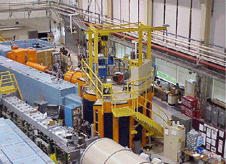 HFBS: Picture of HFBS from the northeast of the guide hall.
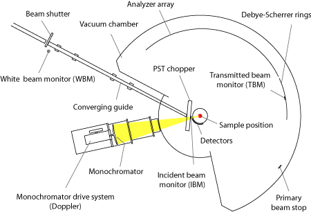 HFBS: Layout of HFBS from bird's-eye view.
The NCNR backscattering spectrometer
A backscattering spectrometer is an inverse-geometry instrument in which only those neutrons with a particular final energy (2.08 meV in this case) are detected in the counting process. The motions in the sample are probed by varying the energy of the incident neutrons (by Doppler motion of the monochromator) and measuring the gain or loss in energy that they undergo in their interaction with the sample.
The backscattering spectrometer at the NCNR is located on neutron guide NG2. The photograph shows the instrument as seen from the north-east corner of the Guide Hall.
The plan view of HFBS shows the major components of the instrument. These will be described in the proceeding sections below.
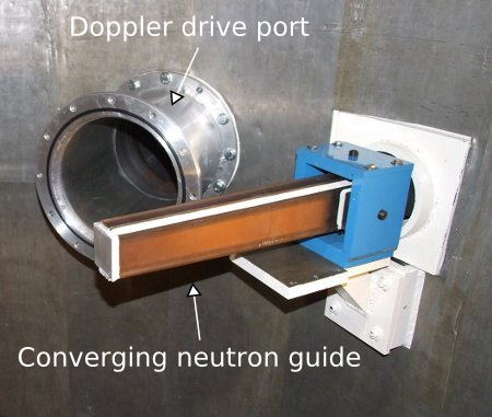 Converging Guide: The converging guide without shielding and also showing the port for the doppler.
Converging neutron guide
The HFBS is located at the end of a dedicated neutron guide, NG2. Neutrons from the source reach the instrument by travelling along an evacuated glass guide 41.1 m in length, with a cross section of 15 cm by 6 cm. The top and bottom interior surfaces are coated with NiCTi supermirrors with a critical angle of reflection given by 4πΘc = Qcλ = (0.044 Å-1) λ, while the interior side surfaces are coated with 58Ni equivalent supermirrors for which 4πΘc = (0.026 Å-1) λ.
About 26 m downstream of the source, a cut in the guide accommodates a neutron velocity selector, and bismuth and beryllium filters. These serve to reduce the background in the instrument by limiting the number of γ- rays and those neutrons with energies outside the usable range of the HFBS.
As the neutrons enter the scattering chamber, a converging guide is used to focus the large beam from the guide down to a size that is commensurate with typical sample dimensions: 2.8 cm wide by 2.8 cm high. The guide entrance is located 41.3 m downstream from the cold source, just after the local beam shutter and before the PST chopper. All four of its interior surfaces are coated with 2&ThetacNi equivalent supermirrors. The overall gain in intensity due to the converging guide is a factor of 3.4 over the beam from the main guide.
 PST: Drawing of PST chopper for illustrative purposes.
 PST: Photo of the PST chopper in the housing, exposed for repair work.
The phase space transformation chopper (PST)
The phase space transform (PST) chopper exploits the physics of Bragg diffraction from moving crystals to shift the neutron energies toward the desired value of 2.08 meV. Neutrons that are diffracted from the rotating PST chopper are Doppler-shifted up or down in energy depending on whether they are less than or greater than 2.08 meV, respectively. Essentially, the PST transforms the shape of the incoming neutron beam in phase space to enhance the flux at the backscattering energy of 2.08 meV at a cost of an increased horizontal divergence (the divergence increases from 3° to 17°).
The idea, developed by Schelten and Alefeld [1], was proposed to address the significant mismatch in divergence between the primary and secondary spectrometer. The HFBS is the first instrument in the world to incorporate such a device.
The PST on the HFBS is a 1 m diameter disk whose periphery is divided into 6 sectors (see photograph reproduced below). Alternate sectors are covered with crystals of highly oriented pyrolytic graphite (HOPG) that are 34.5 mm high, 28.0 mm wide, and 1.5 mm thick. The mosaic spread of an individual crystal is 2.5° and three crystals are stacked together to yield an overall mosaic spread of 7.5°. As seen from the graph above, a rotation rate of 4732 RPM results in the maximum gain of 4.2 times the flux at standstill.
[1] J. Schelten, B. Alefeld, in: R. Scherm, H. H. Stiller (Eds.), Proc. Workshop on Neutron Scattering Instrumentation for SNQ, Report Jul-1954, 1984.
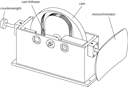 Doppler: Drawing of the doppler cam and monochromator screen assembly.
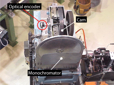 Doppler: Picture of the Doppler from the top of the instrument without the shielding in place.
Monochromator and Doppler drive
The neutrons diffracted from the PST are then monochromated by silicon crystals that are mounted on a support structure that is curved to focus the neutrons onto the sample position. The strain arising from the bending serves to enhance the backscattered flux at the expense of energy resolution.
The HFBS employs a mechanical Doppler drive to produce an oscillatory motion of the monochromator in order to vary the incident energy of the neutrons. The motion is oriented along the average silicon wafer [111] direction so as to maintain the backscattering condition to achieve the sub µeV energy resolution. In contrast to other backscattering spectrometers, the HFBS drive system is a cam-based one which allows the velocity profile of the motion to be determined by the shape of the cam. As implemented on the HFBS, the velocity profile of the monochromator is a rounded triangle. This shape avoids the large accelerations resulting from a pure triangle profile but still allows almost equal weighting to all energy transfers in the dynamic range. This is not possible with a conventional sinusoidal velocity profile (found in locomotive-type drives) which applies more weight to large energy transfers.
The Doppler drive is designed to achieve a top frequency of 25 Hz which corresponds to an acceleration in excess of 100 g's. The support structure is constructed from a graphite composite with a foam core to minimize the total mass of the assembly. In addition, the maximum deflection of the structure at the highest operating speed is designed to be less than 0.25 mm to keep the energy resolution as narrow as possible.
| Support structure | carbon composite with foam core |
| Support structure mass | 0.74 kg (0.95 kg with crystals) |
| Number of crystals | About 15 |
| Amplitude of the motion | 4.5 cm |
| Velocity profile | rounded triangle |
| Crystal thickness | 0.75 mm |
| Monochromator height | 28 cm |
| Monochromator width | 52 cm |
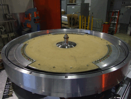
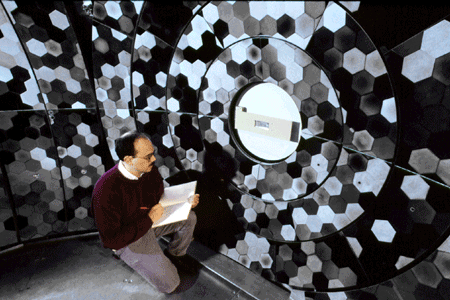 Analyzer: Dan Neumann inspecting the analyzer and Debye-Scherrer rings during commissioning.
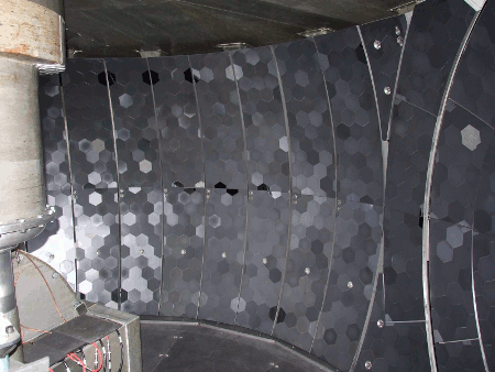 Analyzer: Another view of the analyzer assembly. The sample well and PST can be seen on the left.
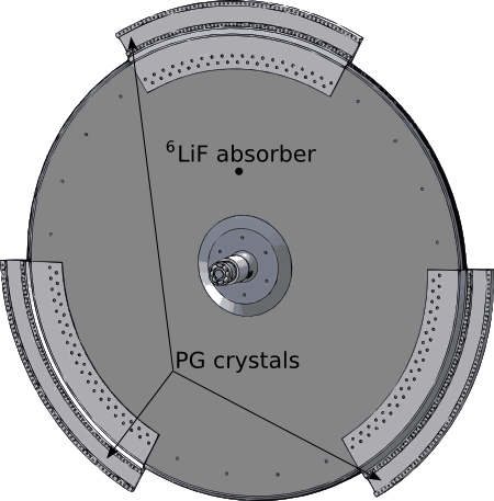
HFBS analyzer crystals
The analyzer assembly on the instrument consists of eight spherically curved segments tiled with hexagonal pieces of silicon wafers. The radius of curvature of the system was chosen so that the neutrons that are diffracted back are focused at the detectors. The system is the largest of any backscattering spectrometer in the world.
In the center of the picture of Dan Neumann inspecting the crystals is the transmitted beam monitor surrounded by the Debye-Scherrer rings. The entire enclosure is evacuated during opperation to reduce the scattering from air. In the other picture we can see the remaining coverage and the sample well and PST housing.
| Crystal thickness | 0.75 mm |
| Assembly height | 201 cm |
| Span | 165° (23% of 4π steradians) |
| Radius of curvature | 2.05 m (focuses at the detectors) |
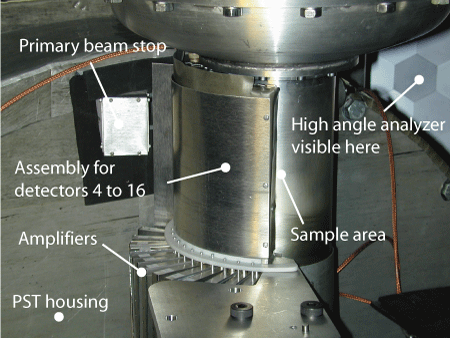 Detectors: View of detectors.
 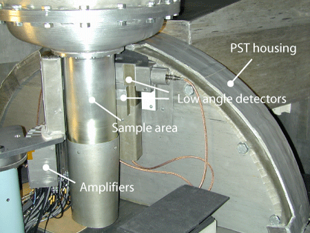 Detectors: Another view of neutron detectors showing the incident beam monitor.
Neutron detectors
The detectors used in the HFBS are pressured 3He detectors, with the exception of a fission chamber that is used to monitor the incident beam.
The following is a list of all the detectors:
Low angle (1 through 3): Three rectangular detectors with 38 mm x 38 mm active area, and 3He fill pressure of 2.5 bar.
High angle (4 through 16): One 25 mm-diameter detector (#4), and twelve 12.5 mm-diameter detectors, with 3He fill pressure of 6 bars.
Monitors: Pencil-type 3He detector to monitor the white beam (white beam monitor, WBM), fission chamber placed to intercept the neutrons just before they hit the sample (incident beam monitor, IBM), and a 3He rectangular detector for the transmitted beam (transmitted beam monitor, TBM), located at the center of the Debye-Scherrer rings (visible in the photograph in the preceding section on the analyzers).
| Detector ID | Angle (2Θ) | Qel (Å-1) | Type |
| WBM | 3He | ||
| IBM 0 | Fission chamber | ||
| 1 | 14.46° | 0.25 | 3He, rectangular |
| 2 | 20.98° | 0.36 | 3He, rectangular |
| 3 | 27.08° | 0.47 | 3He, rectangular |
| 4 | 32.31° | 0.56 | 3He, 25.0 mm |
| 5 | 36.00° | 0.62 | 3He, 12.5 mm |
| 6 | 43.70° | 0.74 | 3He, 12.5 mm |
| 7 | 51.50° | 0.87 | 3He, 12.5 mm |
| 8 | 59.25° | 0.99 | 3He, 12.5 mm |
| 9 | 67.00° | 1.11 | 3He, 12.5 mm |
| 10 | 74.75° | 1.22 | 3He, 12.5 mm |
| 11 | 82.50° | 1.32 | 3He, 12.5 mm |
| 12 | 90.25° | 1.42 | 3He, 12.5 mm |
| 13 | 98.00° | 1.51 | 3He, 12.5 mm |
| 14 | 105.75° | 1.60 | 3He, 12.5 mm |
| 15 | 113.50° | 1.68 | 3He, 12.5 mm |
| 16 | 121.25° | 1.75 | 3He, 12.5 mm |
| TBM | 0° | 3He, rectangular |