
Official websites use .gov
A .gov website belongs to an official government organization in the United States.
Secure .gov websites use HTTPS
A lock (
) or https:// means you’ve safely connected to the .gov website. Share sensitive information only on official, secure websites.
DCS Users' Guide
- Safety matters
- Samples and sample cans
- How thick should my sample be?
- Sample environments
- Beam masks and beam stops
- Instrument computers
- User communication with the instrument
- Runs and sequences
- Miscellaneous
- Data Reduction and Analysis
- Contacts
Please read all of this section if you have not done so previously.
| In normal operation, i.e. with all choppers running, the DCS beam is of relatively low intensity since it is both pulsed and monochromatic. In normal operation exposure to radiation from the beam is practically impossible unless you intentionally (or unintentionally) place part of your body inside the sample chamber with the shutters open. To do so is not easy. Access to the sample chamber is from above or through a side door. The door is interlocked so that the local shutter closes if and when the door is opened more than a few inches. The mezzanine is roughly 1.4 m (~56") above the beam, and this distance is such that radiation levels at the mezzanine are comparable with background. With the local shutter closed the dose rate at the sample position is very low. |
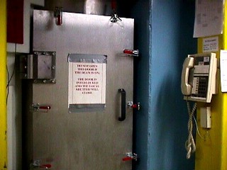 The door to the sample chamber. The notice reads as follows: "DO NOT OPEN THIS DOOR IF THE BEAM IS ON: THE DOOR IS INTERLOCKED AND THE LOCAL SHUTTER WILL CLOSE". |
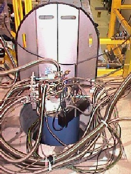 A view of the hole that provides access to the sample chamber from above, with the 11.5 T cryomagnet installed. |
Safety concerns at the mezzanine level
| A large hole in the floor of the mezzanine provides access to the sample chamber from above. Take great care to avoid tripping and/or falling into this hole. Be particularly attentive to placement of cables and hoses. Whenever feasible lower the hinged cover plates, but be particularly careful if you have to reach across the hole to get hold of a cover plate. Depending where ancillary equipment happens to be placed, be sure to use one or both of the chains to hinder access to the area surrounding the hole. |
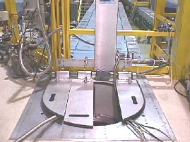 A view of the hole that provides access to the sample chamber, with a "displex" unit installed. |
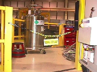 One of the chains used to hinder access to the area surrounding the hole. |
| Do not use the main guide hall crane unless you have received training by an NCNR-approved Research Facility Operations technical staff member.
Do not use the DCS local gantry crane unless you have received NCNR-approved instruction by a DCS instrument scientist. The gate at the West side of the mezzanine (near the main stairs) must remain closed and properly latched at all times, except when it is opened to transfer heavy equipment (such as a helium dewar) between the guide hall floor and the mezzanine. |
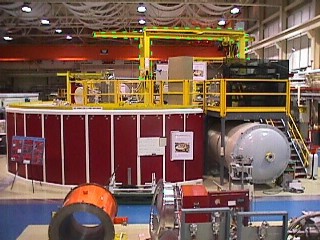 A view of the DCS, showing the local gantry crane outlined in green. |
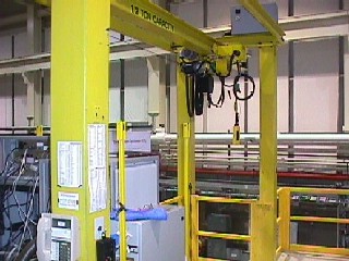 A view of the local gantry crane, and the gate on the West side of the mezzanine. |
Samples vary so much, and in so many respects, that what follows is necessarily incomplete but hopefully still useful. These remarks generally apply to powder samples and liquids in standard geometries. Single crystals, oddly-shaped samples, and samples to be placed in unusual environments such as a high pressure cell, are another story.
The DCS beam is 100 mm high and its intensity is essentially uniform as a function of height. The width of the beam depends on the resolution mode. In low resolution mode it is 30 mm. In medium resolution mode it is 15 mm. The intensity is reasonably constant over the central region but falls off with increasing horizontal distance from the beam center line. Typically the sample should be about as tall as the beam and fairly narrow (15-20 mm). Tall and thin is better than short and fat. We generally use cylindrical or annular sample cans when working with powders, and almost invariably annular cans for liquids. In some cases a flat plate (or some other geometry) may be preferable, or indeed the only practical solution.
With the NCNR's Oxford Instruments 11.5 Tesla vertical magnet dilution refrigerator the available height is restricted to roughly 30 mm. Consult with your local contact if you plan to use this equipment.
 |
The DCS cylindrical cans, currently in short supply, are available with two choices of inside diameter, ~13 mm (0.5") and ~18 mm (0.7"). They can accommodate samples with two choices of maximum illuminated height, either ~81 mm (3.18") or ~113 mm (4.46"). The latter height is generally preferred. For more detailed information consult your local contact. |
 |
The principal components of a DCS annular can assembly are an inner can and an outer can. The annular thickness t is equal to 0.5*(d2 - d1) where d2 is the inside diameter of the outer can and d1 is the outside diameter of the inner can. All outer cans have d2 ~ 20 mm (0.783"). Different values of t are achieved using inner cans with different values of d1. The inner cans with d1 > 18 mm (i.e. t < 1 mm), by virtue of their flanged design, can only be used with liquid samples. The inner cans with d1 <= 18 mm (t >= 1 mm), having a flangeless design, can be used with liquids or powders (as long as the powder is sufficiently fine that it can be introduced into the annular space between the inner and outer cans). The maximum useful height of samples placed in annular cans is h = 100 mm. Theoretical thicknesses t and volumes V, using d2 = 19.89 mm and h = 100 mm, are given in the table below. For additional information consult your local contact. |
| d1 (mm) | t(mm) | V (ml) | Remarks | Availability |
| 19.58 | 0.15 | 0.94±0.16 | Liquids only | Yes |
| 18.95 | 0.47 | 2.87±0.15 | Liquids only | Yes |
| 18.31 | 0.79 | 4.72±0.15 | Liquids only | Yes |
| 17.78 | 1.05 | 6.24±0.15 | Liquids or powders | No |
| 14.73 | 2.58 | 14.02±0.14 | Liquids or powders | Yes |
| It is important to minimize scattering by materials other than the sample itself and those parts of the sample container that are necessarily in the beam. Depending on the sample environment and on personal preference, samples may be masked with cadmium, Gd2O3 paint, boron nitride or some other neutron-absorbing material. Alternatively, or in addition, a beam mask can be employed to restrict the height and/or width of the incident beam. |
How thick should my sample be?
Click here for a discussion of this important topic.
If you have comments please contact John Copley, john.copley [at] nist.gov (<john[dot]copley[at]nist[dot]gov>.)
Commonly used sample environments include two dedicated 70 mm ILL ("Orange") cryostats named DCS1 and DCS2, "low temperature" and "high temperature" NCNR closed cycle refrigerator (CCR) units (commonly known as "displexes"), a dedicated room temperature vacuum vessel, and the NCNR's Oxford Instruments 11.5 Tesla vertical field magnet dilution refrigerator.
You are advised to consult the NCNR's sample environment Web pages for information about the NCNR's sample environment capabilities. Please let us know if you discover inconsistencies between the information given below and the information on the Web.
Mounting the sample within the sample environment device
 |
The center of the sample should be at the same height as the beam center. |
|
If the sample does not have cylindrical geometry, e.g. if it is a flat plate, care must be taken to ensure that it is correctly oriented within the sample environment, taking into account factors that determine or constrain the orientation of the sample environment with respect to the incident beam. |
|
The method of mounting the sample within the sample environment depends on the sample environment. |
 |
Orange cryostats |
|
Displexes |
|
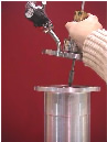
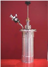
Room Temperature vessel |
|
11.5 Testa vertical magnet dilution refrigerator (For advice on how to mount samples please ask your local contact) |
- The 70 mm Orange cryostat that is normally used at the DCS is 440 mm taller than a standard NCNR 70 mm cryostat. (It is possible to use one of the NCNR's standard cryostats, but to do so requires that special tails be installed so use of a standard length NCNR cryostat is strongly discouraged.)
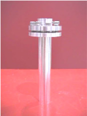
- The sample stick has a male 5/16-UNC thread, 3/8 inch (9.5 mm) long, to which the sample or sample can is attached. We have an adapter piece with a male M8 thread, 9.5 mm long.
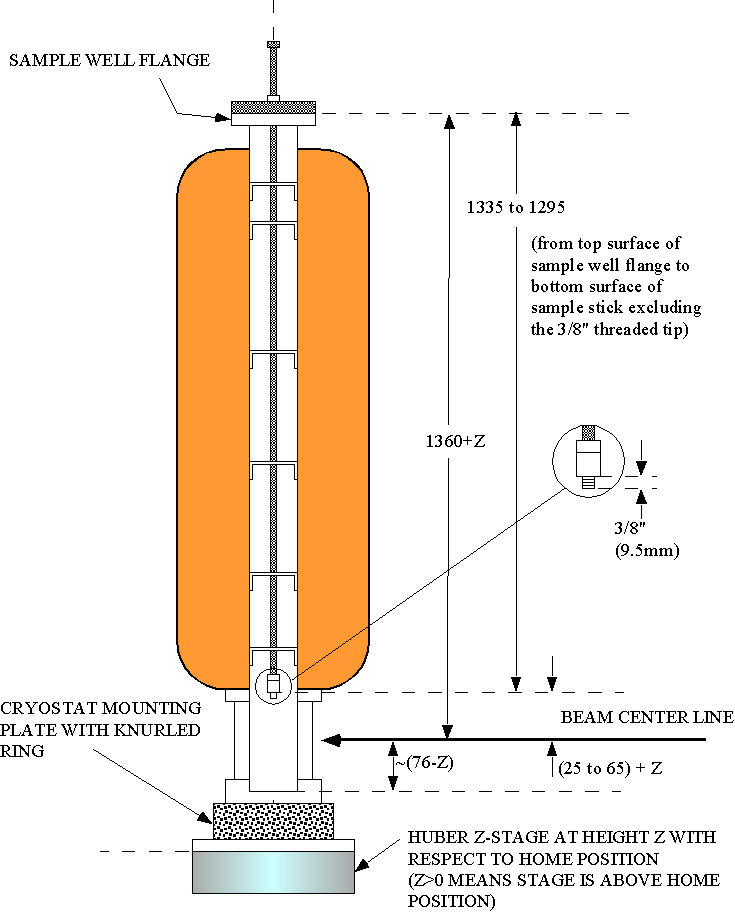
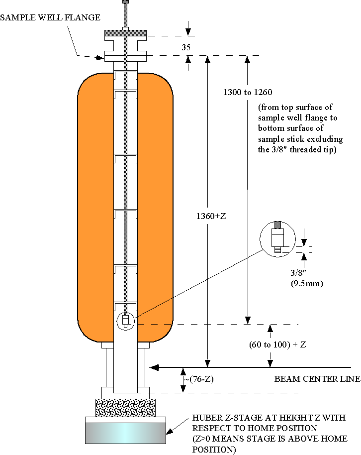
- We have 35 mm extension pieces that effectively increase the height of a cryostat (but do not change the length of the sample stick). Below you will find two figures. Figure 1 shows the setup without the extension piece. Figure 2 shows the setup with the extension piece. Choose whichever setup is best suited to your needs.
| Figure 1. This figure shows the DCS cryostat mounted on the DCS sample stage without the extension piece. With the Huber z stage in its home position the distance from the top flange of the sample well to the beam center line is 1360 mm. The distance from the bottom surface of the sample stick flange to the mounting thread is adjustable from 1295 to 1335 mm. The distance from the top surface of the sample well flange (i.e. the bottom surface of the sample stick flange) to the inside bottom of the cryostat is approximately 1436 mm. Go to Figure 2. |
 |
| Figure 2. This figure shows the DCS cryostat mounted on the DCS sample stage with the extension piece installed. With the Huber z stage in its home position the distance from the top flange of the sample well to the beam center line is 1360 mm. The distance from the bottom surface of the sample stick flange to the mounting thread is adjustable from 1260 to 1300 mm. The distance from the top surface of the sample well flange (from the bottom surface of the sample stick flange) to the inside bottom of the cryostat is approximately 1436 mm (1471 mm). Go to Figure 1. |
 |
The sample (sample can) is attached to a copper sample block that has a tapped bolt circle (four 10-32 holes on a 1.75 inch diameter). The distance D from the bottom surface of the sample block to the sample center is determined, in part, by the height of the outer vacuum can. At the DCS, because of the greater distance between the sample table and the beam center line as compared with many of the other NCNR spectrometers, we use our own vacuum cans and radiation shields. The available outer vacuum cans have a height of either 286 mm or 308 mm. With the sample stage in its home position (z=0), the distance D is 69 mm for the shorter vacuum can (H = 286 mm, see Figure 1), 91 mm for the longer can (H = 308 mm, see Figure 2).
 |
 |
| Mounting scheme with 286 mm vacuum can | Mounting scheme with 308 mm vacuum can |
In this case the sample stick is a male 5/16-18 stud, approximately 3/4 inch long, to which the sample or sample container is attached. One of the two DCS outer vacuum cans (see above) is used, and the height of the sample should be adjusted accordingly. With the sample stage in its home position the sample center should be 154 mm from the bottom surface of the can.
 |
 |
 |
Mounting the sample environment on the DCS sample stage
- Room temperature vessel: The room temperature vacuum vessel is mounted on the sample stage through the sample chamber door. An adapter plate must first be installed.
- Cryostats and Displexes : Cryostats and displexes are mounted from above requiring the use of the local crane. Remember that you may not use the crane unless you have been trained in its operation. An adapter plate must first be installed.
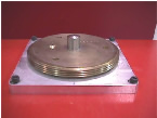
For the ILL cryostat we use an adapter plate fitted with a center pin and an optional ball bearing that determines the orientation of the cryostat. See the photo below.
For the room temperature vacuum vessel and for the displexes we use a different type of plate, with brass pieces that secure the vessel to the adapter plate. See the photo below.
For the 11.5 Tesla vertical field magnet dilution refrigerator, rely on your local contact.
Reminder for the local contact: The optimum sample table height for the dilution refrigerator is -4.4 mm (see February 23, 2003 DCS log book for more details).
 |
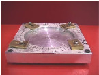 |
| Adapter plate for cryostats. The centering pin is shown in place but the ball bearing is absent. | Adapter plate for the room temperature vessel and displexes. |
At the start of your experiment your local contact will install the sample environment unless you have some experience in this matter from a previous experiment. If you will be changing samples, requiring that you remove and reinstall the sample environment during your measurement time (and that you have received crane training), your local contact will make sure that you understand how to carry out these operations safely.
The following utilities are available on the DCS mezzanine level:
|
Liquid Nitrogen |
|
Compressed air |
|
Helium gas |
|
Chilled water |
|
Various types of electrical power are also available |
 |
We also have several vacuum pumps:
|
High vacuum pump sets (rough pump plus turbo) for pumping out cryostats |
|
A small pump and helium exchange gas facility for cryostat sample well |
|
A pump for helium reservoir |
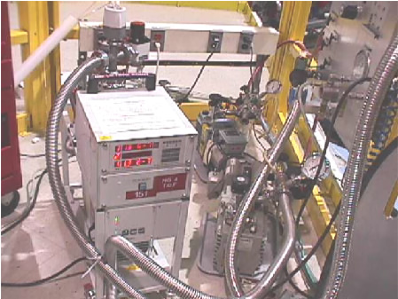 |
| DCS pumps |
Before mounting the sample environment decide an appropriate beam width and height. Two masks may be used to restrict the size of the beam. One controls the width of the and the other controls its height.
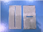 |
| The mask on the left determines the beam width. The mask on the right determines its height |
Beam stops (sorry, not yet available)
|
The Linux control computer called "dcs", IP address dcs.ncnr.nist.gov. |
|
The Linux analysis computer, called "solo", IP address solo.ncnr.nist.gov. |
|
The Windows analysis computer, unnamed. |
|
The chopper computer, sometimes known as "cute". |
The dcs computer is used to set up runs and take measurements, and solo and/or the Windows computer are used to visualize, reduce, and analyze your data (unless you choose to download your data directly to some other computer). To monitor chopper operations you may need to examine the chopper computer screen but you should not need to (and you should not, unless instructed by a DCS instrument scientist) touch its keyboard.
The username for dcs, solo and the Windows computer is "dcs". Your local contact will tell you the password (which is changed periodically).
|
The home directory is /home/dcs |
|
Data for the current reactor cycle are stored in a directory such as /home/dcs/data/200610, or more generally /home/dcs/data/yyyymm where yyyymm designates the reactor cycle, yyyy and mm being the year and month that the reactor cycle started. (The data acquisition software writes raw data files to this directory on dcs, and the update command, involved from solo, may be used to copy these files to the identically named directory on solo.) |
|
The command "cdd" may be used to change to the current data directory. |
Raw data files have names such as 20021017_04.dcs.gz (up to and including calendar year 2002) or 20030218_023.dcs.gz (starting with calendar year 2003), i.e. yyyymmdd_kk.dcs.gz or yyyymmdd_kkk.dcs.gz, where yyyy, mm and dd are the year, month and day that the file was created and kk or kkk is a sequence number. The files are written in a binary format that can be read using software called Octave (which is closely related to Matlab).
Raw data files should only be examined on solo (not on dcs). To read raw data files using Octave they should be unzipped using the gunzip command. Having exited from Octave any unzipped files should be rezipped using the gzip command.
The following commands are useful to the DCS user.
Unless otherwise stated they are typed at the dcs computer.
User communication with the instrument
To communicate with the spectrometer from the dcs computer two applications are provided: dcsgui and dcstalk. (The program called dcs is no longer available.) You will mostly be using dcsgui, but occasionally you may need to use dcstalk. To invoke dcsgui or dcstalk type the appropriate command at the prompt.
|
Computer communication with a temperature controller |
|
The chopper parameters |
|
Setting the chopper parameters |
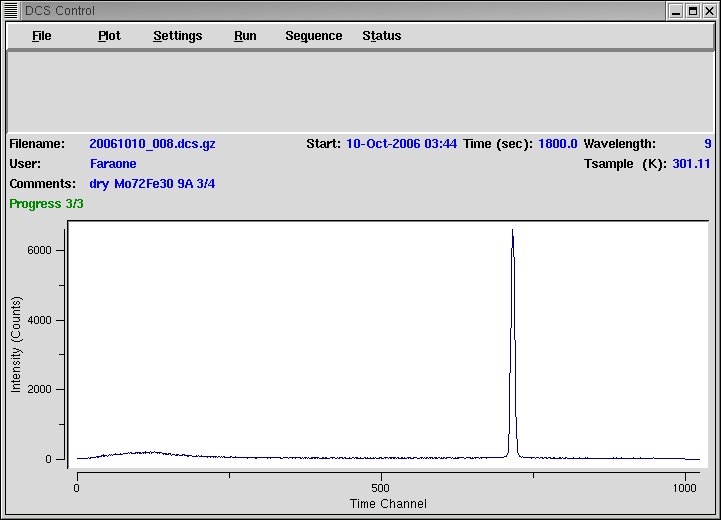
To invoke the dcsgui program type "dcsgui &". The NCNR logo will appear, followed by the DCS Control window:
To exit from dcsgui click "File" and select "Exit"
If you type dcstalk you will get the following type of response:
| $Id: dcstalk,v 1.3 2002/10/04 17:19:45 nickm Exp $ |
| DCS> |
To exit from dcstalk hit the Return key.
Communication with a temperature controller
If you are using a cryostat, a displex, or some other device that uses a temperature controller that can be interfaced to the instrument computer, you should first ensure that the serial line is connected. You should then specify the type of controller in order to establish the communication. To do so, click the Settings menu and select temperature:
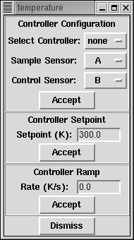 |
The Temperature Control window has three sections. The upper section is used to define the type of controller. The middle and lower sections define the set point and the temperature ramp.
To define the controller (if in doubt ask your local contact), click on the usa-button opposite "Select Controller:" and pick from the list. Select "lk340" if the controller is a Lakeshore model 331 or 340. Be sure to click the "Accept" usa-button to commit your choice. You should see a confirmation message in the top section of the dcsgui control window. If you change the set point you should also look at the displayed set point to satisfy yourself that you have established communication. As further confirmation go to the dcsgui control window, click "Status" and select "Temperature". To close the dcsgui temperature window click the "Dismiss" usa-button. Normally the sample and control sensors are channels A and B respectively. |
|
|
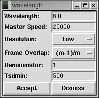
Setting the chopper parameters
| The chopper parameters may be set at any time unless one of the following operations is in progress:
Stopping runs and sequences is described later. If a chopper system shutdown is in progress please talk to your local contact. If the chopper parameters are being set you can abort this operation by going into the dcstalk application and typing "chopctrl abort wavelength". To set the chopper parameters use the dcsgui. Click Settings and select Wavelength: |
 |
|
- Runs
- Sequences
- Defining runs and sequences
- Starting and stopping runs and sequences
- sequence.prm and sequence.log files
Within the DCS control program you can define "runs" and "sequences". A sequence is a set of commands to be executed sequentially when the sequence is started. Arguably the most important of these commands is the command that performs a run.
A run is a measurement using the data acquisition system. In its simplest form it works in the following way:
- The data memory is cleared.
- Data acquisition is initiated.
- At a later time data acquisition is stopped.
- The data are written to a file.
A run normally consists of several "cycles". (The description above applies to a run with a single cycle.) If there is more than one cycle the data are written to the file at the end of the first cycle. Data acquisition then resumes (without clearing the memory), and at the end of the next cycle the file is overwritten with the new data. This process continues until the end of the final cycle.
Having decided the length of a run it is necessary to decide how many cycles the run should comprise. The following remarks may help.
|
If a temperature controller is connected to the control computer and the "Rec Temp" box is checked , sample and control temperatures are recorded in the raw data file at the end of each cycle |
|
If the "Check Stats" box is checked two tests are performed at the end of each cycle. The cycle is rejected if (a) the white beam monitor count rate is less than a specified value (e.g. because the reactor has shut down) or (b) the fractional time that the choppers were out of phase exceeds a specified value. Note that the cycle is lost rather than remeasured so the run will still end at the expected time. |
|
A small amount of time is required to write the data to disk at the end of each cycle. |
|
Typical cycle times are from 5 to 30 minutes (300 to 1800 s). You may wish to discuss cycle times with your local contact. |
As previously stated, a sequence is a set of commands.
Five types of command can be defined within the sequence setup window
There is another set of commands that are not available within the sequence setup window, but these commands can be entered directly into the sequence.prm file.
It is good practice to define your run buffer(s) first and then define your sequence.
To define a run buffer click the dcsgui Run usa-button and select Setup.
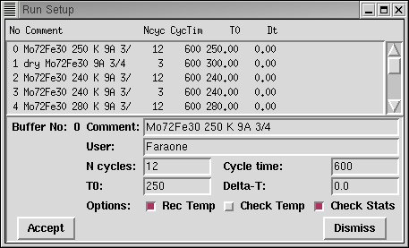 |
In the upper part of the Run Setup window there is a list of 12 "run buffers" numbered from 0 to 11. To edit a run buffer double click on the buffer. The current values of the run buffer parame ters will appear in the lower part of the window:
- Enter a comment.
- Enter your name (or initials) and (optionally) those of your collaborators.
- Enter the number of cycles.
- Enter the cycle time (in seconds).
- Do not worry about T0 or Delta-T; they are not used.
- Check the "Rec Temp" box if a temperature controller is connected to the control computer and you wish to record sample and control temperatures at the end of each cycle.
- Leave the "Check Temp" box unchecked; it is not used.
- Check the "Check Stats" box if you wish to reject cycles that do not satisfy the checks described above. This box should NOT be checked if you are performing a background measurement with the local shutter closed.
- Once you are satisfied click the "Accept" usa-button. To confirm that the parameters have been accepted examine the appropriate entry in the upper part of the window.
- To close the Run Setup window click "Dismiss".
To define (or to edit) the sequence click Sequence and select Setup:
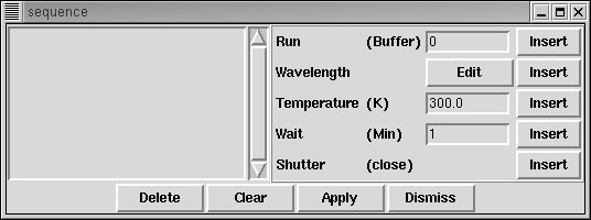 |
- The current sequence is displayed in the left part of the window. To remove all commands from the sequence click the Clear usa-button.
- To delete a single entry in the sequence highlight the entry and then click the Delete usa-button.
- To enter a command, having defined it as discussed below, (if necessary) move the cursor to the appropriate position in the left part of the window and then click the appropriate Insert usa-button on the right side of the window.
- To define a "Run Buffer" command, edit the number of the buffer (to the left of the "Insert" usa-button).
- To define the wavelength command parameters, click the "Edit" usa-button and make the necessary changes as discussed above. Notice that the "Accept" usa-button is disabled because its purpose is to change the current settings immediately rather than at some time in the future. Having defined the wavelength parameters click the Insert usa-button in the wavelength line.
- To define the "Temperature" and "Wait" commands, edit the appropriate parameters.
- At this stage the sequence "known" to the control computer has not been modified. To make it known click the "Apply" usa-button.
- To close the Sequence Setup window click "Dismiss".
The current sequence is contained in an ascii file called sequence.prm in the dcs home directory /home/dcs. This file may be edited by the user but be sure to respect the necessary syntax.
The dryrun command may be used to check the syntax of the sequence file.
Starting and stopping runs and sequences
To start a run, click Run, click Start and select the buffer that you wish to run.
To start a sequence click Sequence and click Start.
If you are doing a run and you want to stop it, click Run and Stop. Choose how you want to stop the run (see below).
If you are doing a sequence and you want to stop it, click Sequence and Stop. Choose how you want to stop the sequence (see below).
If you don't know whether you are running a run or a sequence click Status and select General.
To avoid this confusion it is recommended that you always perform sequences: a sequence can always consist of a single run.
Stopping a run or sequence
There are three ways to stop a run or sequence. In either case we assume that the system is part way through a run cycle.
- Selecting "Now (Lose current cycle)" means that data acquisition will be stopped immediately and data accumulated during the current cycle will be discarded.
- Selecting "Now (Keep current cycle)" means that data acquisition will be stopped immediately and data from the current cycle will be retained.
- Selecting "Later (Finish current cycle)" means that data acquisition will continue until the end of the current cycle and that data from the completed cycle will be retained.
sequence.prm and sequence.log files
As previously stated, the current sequence is contained in an ascii file in the home directory called sequence.prm. As commands are read from this file they are removed from the file so that at any given time after the sequence has started the next command to be performed is the first command in the file. A file called sequence.log, in the home directory, lists the sequence commands that have been executed to date.
Checking that the choppers are in phase
When you return from activities elsewhere it is advisable to check that the choppers are in phase. Ask your local contact.
It is also a good idea to ceck that the white beam monitor count rate is normal. Again ask your local contact.Check list before starting a measurement
Is the sample in the sample chamber?
Is the sample table at the desired height?
Is the temperature controller (if in use) connected to the DCS computer?
Are the sample environment conditions OK?
Are appropriate mask(s) installed?
Is the radial collimator raised and oscillating?
Is the local shutter open?
Is the sequence correctly defined?
Are the choppers phased correctly?The Radial Collimator
The radial collimator is normally oscillated so that any shadowing of the detectors is uniformly distributed. To move any of the other motors you must first stop oscillating the collimator, restarting it when you're done. There may also be situations where the collimator must be lowered and then raised (in which case you must first ensure that the collimator is not oscillating). To perform tasks involving the radial collimator click the dcsgui Settings usa-button and select Collimator.To start or stop oscillation, or to raise or lower the collimator, click the appropriate usa-button.
To close the collimator window click Dismiss.
Use of the log book
Sorry, not yet available.
Beam monitors
Sorry, not yet available.
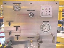
Guide vacuum monitoring system
Click here for a description of the guide vacuum monitoring system.
Miscellany
To restart the Time to Digital Converter daemon, make sure that you have killed the core program and the program liveplot. Then run the following script:
sudo /usr/local/bin/restarttdcd
Typing check_daemon at the prompt should return something like the following:
4 S root 13970 1 2 80 0 - 8237 ? Mar27 ? 00:38:27 /usr/local/dcs/bin/tdcd
0 S ncnr 15363 15323 0 80 0 - 1088 - 14:25 pts/22 00:00:00 grep tdcd
Typing check_usb at the prompt should return something like the following:
crw-rw-rw-. 1 root dialout 188, 0 Mar 28 14:22 /dev/ttyUSB0
crw-rw-rw-. 1 root dialout 188, 1 Mar 28 14:23 /dev/ttyUSB1
crw-rw-rw-. 1 root dialout 188, 10 Mar 27 16:36 /dev/ttyUSB10
crw-rw-rw-. 1 root dialout 188, 11 Feb 18 14:55 /dev/ttyUSB11
crw-rw-rw-. 1 root dialout 188, 12 Mar 28 14:23 /dev/ttyUSB12
crw-rw-rw-. 1 root dialout 188, 13 Feb 18 14:55 /dev/ttyUSB13
crw-rw-rw-. 1 root dialout 188, 14 Feb 18 14:55 /dev/ttyUSB14
crw-rw-rw-. 1 root dialout 188, 15 Feb 18 14:55 /dev/ttyUSB15
crw-rw-rw-. 1 root dialout 188, 2 Mar 28 14:23 /dev/ttyUSB2
crw-rw-rw-. 1 root dialout 188, 3 Mar 28 14:23 /dev/ttyUSB3
crw-rw-rw-. 1 root dialout 188, 4 Mar 28 14:23 /dev/ttyUSB4
crw-rw-rw-. 1 root dialout 188, 5 Mar 28 14:23 /dev/ttyUSB5
crw-rw-rw-. 1 root dialout 188, 6 Mar 28 14:23 /dev/ttyUSB6
crw-rw-rw-. 1 root dialout 188, 7 Mar 28 14:23 /dev/ttyUSB7
crw-rw-rw-. 1 root dialout 188, 8 Feb 18 14:55 /dev/ttyUSB8
crw-rw-rw-. 1 root dialout 188, 9 Feb 18 14:55 /dev/ttyUSB9
Go to the table of contents