Official websites use .gov
A .gov website belongs to an official government organization in the United States.
Secure .gov websites use HTTPS
A lock (
) or https:// means you’ve safely connected to the .gov website. Share sensitive information only on official, secure websites.
DCS Design Features and Principal Specifications
Overall Plan
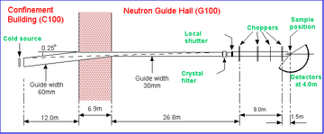
The NG4 neutron guide incorporates an "optical filter" that removes almost all of the high energy neutrons and gamma-rays in the initial section of the guide. After an auxiliary cooled graphite filter and local shutter there are seven disk choppers that collectively produce clean monochromatic bursts of neutrons at the sample position. The sample is located in a large sample chamber, accessible from above and from the side. A radial collimator reduces scattering from the sample environment. The flight chamber is filled with argon gas at atmospheric pressure to reduce the possibility of gas scattering. Each of the 15 detector racks holds three rows of 3He detectors and amplifier-discriminators. The data acquisition system timestamps each neutron event, attaches the detector number, and histograms the information in up to 1024 time channels.
The Primary Spectrometer
- High energy neutrons and gammas from the cold neutron source are removed using an optical filter supplemented by a cooled graphite filter.
- A cleanpulsed monochromatic neutron beam is produced using seven disk choppers.
- Incident wavelengths range from ~0.23 to ~1.0 nm, i.e. ~2.3 to ~10 Å
- Chopper speeds may be varied from 1200 to 20000 rpm.
- Each of the pulsing and monochromating choppers has three slots of different widths. This permits three choices of resolution at a given wavelength and master chopper speed.
- The chopper phase stability is excellent, of order 100-200 ns at 20000 rpm.
- A white beam fission chamber monitors the beam at the local shutter, downstream from the crystal filter, upstream of the choppers.
- A low efficiency 3He beam monitor is placed at the entrance to the sample chamber.
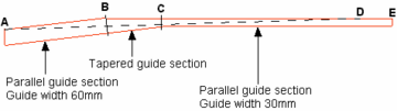
The NG4 neutron guide within the confinement building is 60 mm wide and 150 mm high. Approximately 12 m from the start of the guide, at B, an asymmetric taper is introduced as shown in the attached figure, such that after a further ~6.9 m, at C, the guide width is reduced to 30 mm. Thereafter the guide has parallel sides once again, but its direction has been rotated through ~0.25 degrees. All points beyond point D, which is ~25.3 m from C, are such that there is no line of sight to the guide entrance. The guide ends at E, ~26.0 m downstream from C.
The top and bottom surfaces of the guide are coated with a supermirror coating that has twice the critical angle of natural nickel at any given wavelength. The side surfaces are coated with a multilayer coating such that the critical angle for total reflection is about 1.2 times that of natural nickel at any given wavelength. The idea of the optical filter is that since there is no line of sight to the source from the end of the guide neutrons and gamma rays cannot reach the end of the guide unless they have been reflected or scattered. To further condition the beam, roughly 0.5 m upstream from the local shutter there is a liquid nitrogen cooled pyrolytic graphite filter made of eleven 40 mm wide by 110 mm high "filter grade" ("ZYH") blocks, stacked with their short dimension parallel to the beam. The total length of the filter is 100 mm. For a detailed explanation, please look at the reference The optical filter of the disk chopper spectrometer at NIST JRD Copley and JC Cook (2000) Physica B 283 386-388.
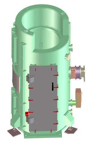
The Sample Area
- The inside diameter of the sample chamber is ~870 mm.
- The sample chamber is readily accessible from above and from the side.
- The beam at the sample position is 30 mm wide (in the "low" resolution mode of operation), 100 mm high.
- Sample table with 3 translation stages, in-plane rotation, and 2(rarely used) tilt stages.
- An oscillating radial collimator, inside radius 200 mm, outside radius 300 mm, inside height 250 mm, consisting of 84 Gd2O3-painted blades with separation 2°, is used to reduce the scattering from sample environment structures.
The Secondary Spectrometer
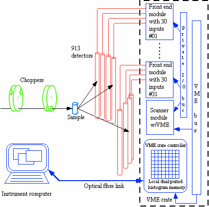
- There are 913 six atmosphere 3He detectors, covering ~0.65 steradians and arranged in three banks:
- The middle bank detector scattering angles range from -30° to -5° and from +5° to +140°
- The upper and lower bank detector scattering angles range from -30° to -10° and from +10° to +140°
- There is continuous coverage in detector scattering angle; there are no gaps due to support structural members.
- The flight distance from sample to detectors is 4010 mm.
- The flight chamber, inside radius 615 mm, outside radius 3905 mm, is purged with argon.
- The window between the sample chamber and the flight chamber is made of 0.001" (0.025 mm) aluminum foil.
- The window between the flight chamber and the detectors is made of 0.00035" (0.009 mm) aluminum foil.
- A rectangular tube, internally and externally lined with cadmium, and ~3260 mm in length is placed in the space between the windows of the flight chamber, in line with the incident neutron beam.
- A fission chamber beam monitor is installed in line with the incident neutron beam, 4054 mm from the sample position. A beam stop is placed immediately downstream of this fission chamber.
Data Acquisition Hardware and Software
- VME-based data acquisition boards generate 32-bit event words with time channel and detector channel information. Each event word is passed to the data acquisition computer which increments the appropriate address in a 2-dimensional data histogram.
- The histogram is stored in a 4 Mbyte reflective memory module that communicates via fibre optic cables with a second 4 Mbyte reflective memory in the instrument control computer.
- The data acquisition software allows users to define sequences that include "runs", wavelength changes, temperature changes and wait periods. A run is broken into "cycles"; at the end of each cycle the accumulated dataset for the completed cycles is backed up to the disk.