
Official websites use .gov
A .gov website belongs to an official government organization in the United States.
Secure .gov websites use HTTPS
A lock (
) or https:// means you’ve safely connected to the .gov website. Share sensitive information only on official, secure websites.
Summary
Our aim is to develop the metrology for quantitative measurements of magnetic properties, including properties and property distributions in multilayer systems. To this end, we have studied magnetic materials from 0D to 3D, ranging from metallo-organic frameworks, nano-objects, including nanoparticles and nanowires and polymer-magnetic nanoparticle nanocomposites for biomedical applications and thermometry, thin films for spintronics applications and nanomagnetic logic, and bulk materials for the magneto-caloric effect, as permanent magnets, as ultra-soft magnets, as spin glasses, and as superconductors. This aim is currently applied to create the foundations for the development of (1) magnetic nano-objects (MNOs) for SI traceable thermometers for remote temperature measurements and (2) magneto-caloric materials and instrumentation for more efficient and environmentally friendly magnetic refrigeration.
Description
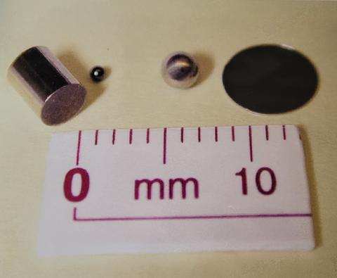
Photo of the magnetic moment and susceptibility SRMs - (left-right) Platinum cylinder, YIG sphere, Ni sphere, and Ni disk
Currently, the bulk of this project is focused on three main pieces:
- Thermal MagIC: An SI-Traceable Method for 3D Thermal Magnetic Imaging and Control
- Magnetic Refrigeration
- Magnetic Standard Reference Materials (SRMs)
- Thermal MagIC (MAGnetic Imaging and Control) is focused on developing new synthetic methods for, and new measurement methods and instrumentation to characterize, multilayered MNOs with high thermosensitivity and signal to noise and controllable magnetic properties.
- Materials: Development of synthetic methods (electrochemical and organic solution synthesis) for multilayer magnetic nano-objects with high thermosensitivity and signal to noise and controllable magnetic properties with narrow property dispersions
- Instrumentation and Methods: Development of quantitative DC and AC measurement methods/instrumentation for characterizing magnetic nano-objects.
- Magnetic Standard Reference Materials (SRMs) is focused on supporting existing SRMs, improving the accuracy and precision of the most sensitive SRM (YIG sphere), and developing new SRMs.
- Assisting users of existing SRMs with questions, applications, and proper usage.
- Examining measurement method and materials to determine if improvements in accuracy and precision can be obtained with advances in technology and accounting for additional uncertainties.
- Magnetic Refrigeration is focused on magneto-caloric effect (MCE) materials (development of structure-property relationships for large operating range MCE materials) and new instrumentation and measurement methods (for quantitative measurement with uncertainty of refrigeration capacity and how it relates to calculated values by other methods).
Major Accomplishments
For recent results on Thermal MagIC, please see: Thermal MagIC: An SI-Traceable Method for 3D Thermal Magnetic Imaging and Control.
Radial Offset and Length Dependence of Measured Moment of a Sample in MPMS and MPMS3
For metrology, measurement reproducibility is critical. We studied the reproducibility of measurements on a second-order gradiometer configuration, which is widely used in magnetometers. Here, we determined the error induced by rotational offset and sample length using YIG spheres and Ni rods on both the MPMS and MPMS3.
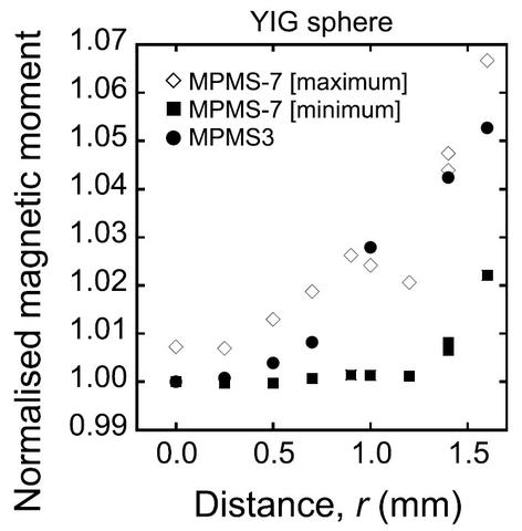
In theory, when the center of sample and the center axis of the pick-up coil of the second-order gradiometer are the same, the observed magnetic moment is at a minimum. In practice, neither the pick-up coil nor the sample rod is perfectly symmetrical/straight. We obtained good reproducibility of the measured values with a relative standard deviation of 0.1% in the SQUID magnetometer by rotating the entire sample rod 360 degrees and using the minimum value from the angular measurement. The rotation operation made up for any lack of straightness of the sample rod and/or pick-up coils used to mount the sample.
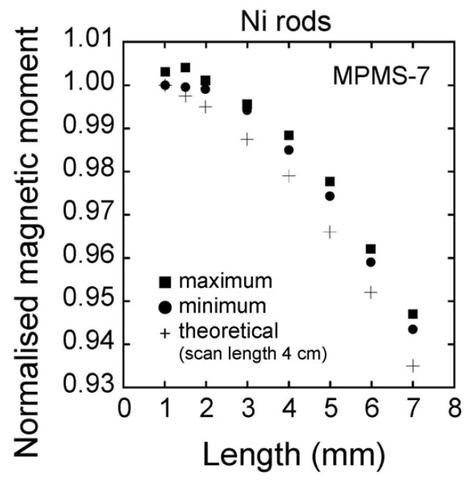
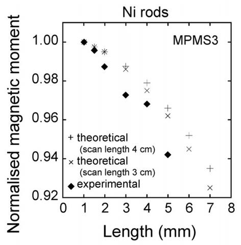
The sample length dependence is likely due to the dipole approximation critical to this measurement method becoming less accurate with increasing length. For the MPMS, the normalized magnetic moment seems to be almost constant for sample lengths between 1 and 2 mm and then significantly decreases as the length increases. The normalized moment for the 5 mm sample is approximately 97% of that of the 1 mm long sample. For the MPMS3, the normalized moment for the 5 mm sample is approximately 94% of that of the 1 mm long sample; the normalized magnetic moment decreases more rapidly than in the MPMS. The difference in sample length dependence between the two models of SQUID may be caused by differences (radius and length) in the configuration of the second-order gradiometer. In practice, a sample length correction is apparently necessary for sample lengths exceeding 2 mm. We are currently working on a method to account for this, so that the raw data can be corrected for measured magnetic moment values of various samples with longer lengths than the 1 mm diameter of the YIG sphere SRM.
First Order Reversal Curve Analysis of Magnetic Tunnel Junctions
We have applied a new method for First Order Reversal Curve (FORC) analysis that is particularly well suited for the study of unpatterned films, because it does not require smoothing in field and therefore can resolve the very sharp structures due to domain wall motion that are typically seen in the FORC diagrams of unpatterned films. It also allows us to visualize the reversible and irreversible parts of the system together, without making an artificial distinction between reversible and low-coercivity materials.

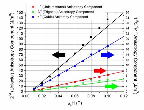
Origin of Anomalous Magnetic Anisotropy in Magnetic Nanoparticles
We observe a magnetic behavior in magnetic nanoparticle dispersions which is distinct from the cubic magnetocrystalline anisotropy of the magnetic material (Fe3O4). Instead, this distinct behavior has its origins in the magnetic interactions among the mobile nanoparticles within the colloid. Specifically, we observed that the onset of a field-dependent colloidal uniaxial anisotropy coincides with chain formation parallel to the direction of the external magnetic field. At even higher fields, the onset of colloidal unidirectional and trigonal anisotropies occurs simultaneously with chain compression into columns and chain zippering (for close packing) perpendicular to the field direction. These anisotropies are distinct from the cubic magnetocrystalline anisotropy measured for bulk Fe3O4 because (a) there is no uniaxial, unidirectional, or trigonal anisotropy present in bulk magnetite; and (b) the measured colloidal uniaxial anisotropy is approximately 100-fold greater than the measured magnetocrystalline cubic anisotropy, which is approximately 4% that of the bulk value for magnetite. These observations suggest that field-induced changes of the physical structure of dilute magnetic colloids can lead to dramatic changes in their composite magnetic properties, presumably arising from competing magnetostatic and steric interactions. The results can be used to guide further development of models useful in many applications that utilize static and alternating magnetic fields, such as magnetic particle imaging, hyperthermia, in vitro assays, and shock absorption. Insights gained also provide new understanding to identify fundamental magnetic origins of the seemingly contradictory findings that magnetic nanoparticles in FFs exhibit anomalously large and small magnetocrystalline anisotropies, as compared to the bulk value, as well as unique magneto-physical properties, such as the asymmetric sound propagation observed in concentrated MR fluids, and the overestimation of the transverse magnetization in rotating MR colloids.
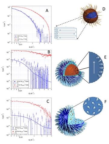
Design Considerations for Magnetic Nanoparticles for the Cancer Treatment Hyperthermia
When combined with other treatments such as radiotherapy or chemotherapy, heat (hyperthermia) applied directly to tumors helps increase the effectiveness of those types of treatments, thereby reducing the necessary dose of chemicals or radiation. To generate this heat, magnetic nanoparticles are exposed to an alternating magnetic field. However, it turns out the amount of heat generated by the magnetic nanoparticles depends upon their physical and magnetic structure. This impacts the thermal dose delivered, and therefore, the magnetic nanoparticle's effectiveness.
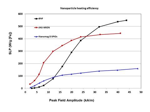
We studied three kinds of iron oxide nanoparticles, each of which had a different internal structure. In the bionized nano-ferrites (BNFs), iron-oxide crystals are stacked neatly, like bricks in a wall; in the magnetic iron oxide nanoparticles (MIONs) from Johns Hopkins University (JHU), the arrangement of crystals is more haphazard, like a pile of balls thrown into a corner; in the nanomag-D spios (SPIOs), the crystals were randomly dispersed over a large area, like plums in a plum pudding. While subjecting all three types to an alternating magnetic field, the BNFs needed a stronger field than expected to heat up, but ultimately generated more heat at higher AC magnetic field magnitudes. The JHUs got hot more quickly, even when the field was still weak. Finally, the SPIOs never generated much heat under any applied AC magnetic fields that were applied. The differences lay in the interactions between atoms within the magnetic nanoparticle and interactions between nanoparticles. The BNFs formed magnetic domains within a single nanoparticle, that had to be re-aligned parallel to each other before significant heat could be generated. Due to interactions between the magnetic nanoparticles, they also experienced collective behavior which resulted in significantly more heat being generated, once the AC magnetic field was larger enough to overcome the magnetic anisotropy (especially colloidal anisotropy described above.) The JHUs for a single magnetic domain in the core of the nanoparticle, but had a shell of mis-aligned domains. This meant heat could be generated at lower fields because the bulk of the magnetic moment was already aligned, but the mis-aligned shell could not be aligned with the amplitude of AC magnetic field applied, reducing the overall amount of heat generated. The SPIOs had crystals with minimal interactions, so there was no collective behavior between nanoparticles, and minimal interactions between crystals. This meant that little heat could be generated at all.
Influence of Grain Constraint on the Magneto-Caloric Effect

We demonstrated that increasing the grain size to thickness ratio of Ni45Mn40Co5Sn10 ribbon samples by annealing heat treatments can decrease the magnetic field requirement for magnetic refrigeration by as much as 3 T under the annealing conditions studied. It is expected that the magnitude of field savings can be even larger with further grain growth. The average grain size increased with annealing time and temperature, which decreased the martensite transition temperature range due to reduction in the density of interfaces. The temperature transition range for the austenite, on the other hand, did not exhibit a significant trend. This improved the refrigeration capabilities of the Ni45Mn40Co5Sn10 by making the structural transformation between paramagnetic austenite and non-magnetic martensite more attainable with smaller fields. This decrease in the field requirement ultimately led to a larger magnetocaloric entropy change achieved under relatively smaller magnetic field levels. The giant inverse magnetocaloric effect of the optimized alloy was measured and showed that up to 25 J/(kg-K) was generated by driving the martensitic transition with magnetic fields up to 7 T.

Development of Good Soft Magnetic and High Strength Materials
With the aim of developing a new Fe-based alloy with good soft magnetic properties and/or ultrahigh strength, we examined the formation ability, thermal stability and properties of an amorphous phase in melt-spun Fe-rich Fe82-85B13-16Si1Cu1 alloys. The results obtained are summarized as follows:
- An amorphous phase was formed in the low B content range of 13–16 %B and high B/Si content ratios above 13. The addition of 1%Cu was found to be essential for the formation of the 13B amorphous alloy, while no amorphous phase was formed for alloy 13B containing 1%Nb.
- Good soft magnetic properties were obtained in both the annealed amorphous state as well as in the nanoscale α-Fe+amorphous mixed state.
- The Vickers hardness value is 867 for alloy 13B and decreases to 803 for alloy 16B. Vickers hardness increases significantly during the phase change to α-Fe+amorphous phases and reaches 1370–1550 after annealing.
- The highest Vickers hardness for the Fe-B-Si-based amorphous alloys without Cu is about 1200 and the addition of 1%Cu was also found to be essential for the achievement of the ultrahigh hardness values.
The findings that the Fe-B-Si-Cu alloys exhibit good soft magnetic properties in both the annealed amorphous and amorphous + α-Fe phases as well as ultrahigh Vickers hardness values exceeding 1550 in the α-Fe+amorphous phase material are promising for further extension as improved soft magnetic and high strength materials having a simpler Fe-rich alloy composition.
SRM 772a Magnetic Moment Standard - Nickel Sphere
SRM 762 Magnetic Moment Standard - Nickel Disk
SRM 764a - Magnetic Susceptibility Standard - Platinum Cylinder
SRM 2853a - Magnetic Moment Standard - Yttrium Iron Garnet Sphere (forthcoming)
Project Summary (PDF)