
Official websites use .gov
A .gov website belongs to an official government organization in the United States.
Secure .gov websites use HTTPS
A lock (
) or https:// means you’ve safely connected to the .gov website. Share sensitive information only on official, secure websites.
Atom Probe Tomography (LEAP 4000X Si/HR – Local Electrode Atom Probe)
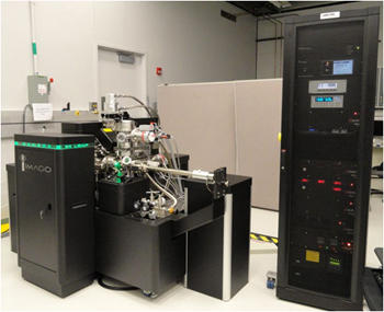
LEAP 4000X Si/HR
- Imaging time-of-flight mass spectrometer and field ion microscope.
- Can deliver 3-D, isotopically- and chemically- resolved images
- Sub-nanometer spatial resolution possible
- High combined efficiency (100% ionization / 55% detection)
- High Sensitivity (approx. 10 ppm at.)
- Typical analysis volume approx. 100 nm x 100 nm x 300 nm.
- No matrix corrections or sensitivity factors required for quantification
Specifications/Capabilities
How it Works

- Atom probe tomography requires samples that are small and needle-like in form. Typically, we prepare the samples in our dual beam FIB/SEM instrument via in-situ, site-specific lift out.
- The sample is loaded into the LEAP analysis chamber, cooled to cryogenic temperatures, and positioned in front of a local electrode.
- A high electric potential is applied between the sample and the local electrode to promote field evaporation and to accelerate any ions down the flight path and towards a 2-dimensional position sensitive detector.
- Data acquisition proceeds by subjecting the sample to repeated pulses, either voltage or thermal (UV laser), to trigger the controlled field evaporation of ions from the sample tip.
- The detector records the time-of-flight and the X and Y impact position on the detector for each ion. Using this information, the identity of each ion is known (mass-to-charge state ratio) and the point of origin on the sample surface can be determined. The Z depth for each ion is determined by order of arrival.
- A 3-D reconstruction of the sample is generated, atom-by-atom, by computer.
Typical Outputs
- 3-D, chemically- and isotopically- resolved images

- Time-of-flight and mass spectra

Site-Specific Atom Probe Sample Preparation via Dual Beam FIB-SEM


Usage Information
Access Information
Collaborative research projects are possible when the work is consistent with the Materials Measurement Science Division mission and interests. Please contact us to discuss possible collaborations.
Created January 11, 2012, Updated May 15, 2023