
Official websites use .gov
A .gov website belongs to an official government organization in the United States.
Secure .gov websites use HTTPS
A lock (
) or https:// means you’ve safely connected to the .gov website. Share sensitive information only on official, secure websites.
Mercury Thermometer Alternatives: Platinum Resistance Thermometers (PRTs)
Platinum Resistance Thermometers (PRTs) rely on the fact that platinum, like many other metals, exhibits increased electrical resistance as temperature rises. For example, a conventional PRT designed to provide 100 Ω at 0 °C has a resistance in the neighborhood of 80 Ω at -50 °C and 120 Ω at 50 °C, or a sensitivity of about 0.4 Ω per degree. PRTs constructed to particularly exacting specifications, termed Standard Platinum Resistance Thermometers (SPRT), are named as the defining measurement tools for interpolating temperatures under ITS-90. In general, PRTs can have high accuracy (0.01 °C), stability, and repeatability across a wide range of temperatures from -200 °C to 500 °C.
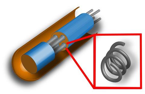
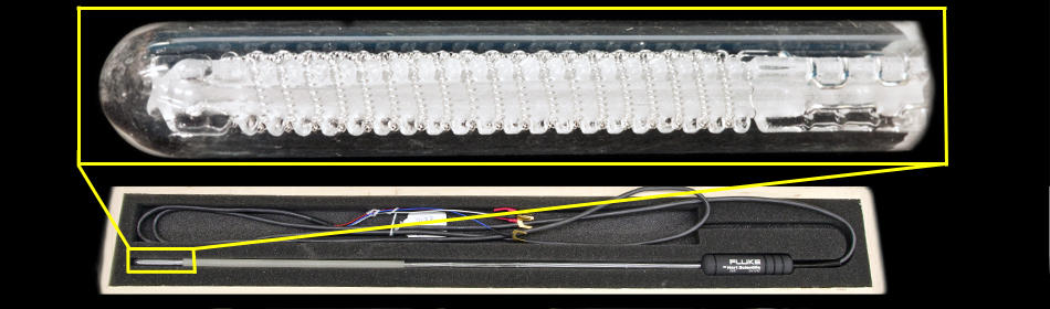
Typically the platinum element is formed into thick or thin films, or the platinum wire is arranged in two, three or four helical coils (see diagram, right) – the more coils, the higher the sensitivity. The film or wire is placed inside a glass or ceramic enclosure, and can be supported by loose or compacted MgO. Platinum-based leads connect the probe unit to the thermometer electronics, which convert the electrical signal to temperature.
PRTs are broadly divided into two groups: Industrial PRTs (IPRTs) and SPRTs, depending on sensitivity and robustness. ASTM and IEC define several classes of PRTs, each with a different set of specifications. An ASTM "Class A" unit, for example, has an out-of-the-box tolerance — maximum permissible error — that ranges from 0.47 °C at -200 °C to 0.13 °C at 0 °C to 0.98 °C at 500 °C.
Users considering an IPRT should consult ASTM E1137 for standards and specifications.
NIST calibrates these devices from -196 °C to 550 °C
Advantages
- Wide temperature range
- Resistance-temperature relationship is well characterized.
- Rugged construction in IPRTs
- Cost of an IPRT is less than an SPRT.
- Available in different shapes and sizes – application specific
- Can be used with a digital temperature read-out device.
Disadvantages
- Mechanical shock and vibration will cause drift.
- Deterioration at elevated temperatures (e.g., >500 °C)
- 2- and 3- wire devices need lead-wire compensation.
- Non-hermetically sealed IPRTs will deteriorate in environments with excessive moisture.
- Not as accurate as an SPRT
Any mention or image of commercial products within NIST web pages is for information only; it does not imply recommendation or endorsement by NIST.
Contacts
-
Questions about Mercury Thermometer Alternatives?