
Official websites use .gov
A .gov website belongs to an official government organization in the United States.
Secure .gov websites use HTTPS
A lock (
) or https:// means you’ve safely connected to the .gov website. Share sensitive information only on official, secure websites.
Simple and Inexpensive FPGA-based Fast Multichannel Acquisition Board
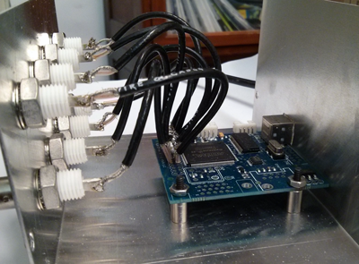
This project allows investigators to build their own data acquisition instruments to collect and statistically process data in real time, then send the results to a PC via USB 2.0 from a board built around a field-programmable gate array (FPGA) chip. Users can access data through a set of National Instruments' LabVIEW VIs, or directly through an included dynamic-link library (DLL). The user can access the collected data on request from the FPGA board, and can use this data in custom applications. This is the second iteration of the project; the main upgrade is a transfer to USB drivers which work with Windows 7, 32- and 64-bit platforms. However a few other improvements and additions have been made also.
(For the previous version of the project, click here).
This instrument was built to perform pulse time stamping and multiple coincidence detection for single photon detection and statistical analysis in quantum information experiments. However, users can modify the data collection algorithm to create a custom instrument. Because data transfer protocols are already written and debugged, users can significantly decrease development time. At the same time, the project requires a minimal investment in hardware with the bulk of the cost in an inexpensive and commercially available FPGA testing board which requires no significant modifications. Setup requires only software installation, and wiring and mounting the board, which involves basic soldering and hole-punching or drilling sheet metal.
The platform is based on a Xylo-EM board built by knjn and consists of four parts.
1. Our FPGA firmware. Two varieties are included: one incorporates a data collection algorithm for collecting click and coincidence data; the other does detailed time-stamping. Each also includes two user-controlled TTL output channels, and handles the data transfer protocol through a Cypress FX2 chip for USB 2.0 connectivity.
2. Cypress FX2 driver for Windows 7 32- and 64-bit (knjn also provides this driver with the Xylo-EM board) to support USB 2.0 connectivity from the computer to the FPGA board.
3. LabVIEW VIs (2013, 2012, 2011 editions) to handle the coincidence and time-tagging data acquisitions and TTL pulse generation.
4. Our C++ code (mid-level driver) and compiled DLL that receives the acquired data and prepares it for the LabVIEW interface in real time.
The end-user can customize the code to process and/or graph the received data.

Description of Functionality
Counts: Multiple Coincidence Statistics
Purpose and function:
- Collects data from 4 TTL sources and registers single events and coincidence events.
- Accumulates statistical information on these events in hardware and uploads this information to a computer on demand.
- No time tagging information is collected, so data exchange with a computer is minimized.
- Works with internal 48 MHz clock, or external clock up to 96 MHz (possibly higher).
- Two channels may toggle TTL output, or output one clock-cycle TTL pulses.
Time Tag: Time-tagging multiple-coincidence detector
Purpose and function:
- Collects data from 4 TTL sources and time-tags the first incidence of the TTL high during a clock rising edge for each channel.
- Detects coincident positive edges (within one time bin).
- Outputs time-tags of events when one or more channels changed their state from TTL low to high.
- One-clock cycle dead time.
- Works with internal 48 MHz clock, or external clock up to 96 MHz (possibly higher).
- External TTL or a computer-controlled input restarts the clock (i.e. a "start" channel).
- Two channels may toggle TTL output, or output one clock-cycle TTL pulses.
Contact
-
(301) 975-8473