
Official websites use .gov
A .gov website belongs to an official government organization in the United States.
Secure .gov websites use HTTPS
A lock (
) or https:// means you’ve safely connected to the .gov website. Share sensitive information only on official, secure websites.
Standard Bullets and Cartridge Cases
When a firearm is fired, it leaves toolmarks on the spent bullet and cartridge case. By analyzing and comparing these toolmark signatures, forensic examiners may be able to link a bullet or cartridge case found at a crime scene to a particular firearm or another crime scene. The NIST standard bullets, Standard Reference Material (SRM) 2460, and standard cartridge cases, SRM 2461, have been developed as reference standards for forensic laboratories to help verify that equipment used to acquire images of the firearm toolmarks is operating properly and to facilitate measurement traceability and laboratory accreditation. They have been tested in volunteer crime laboratories across the country for the purpose of developing quality control procedures for image acquisitions in the National Integrated Ballistic Information Network, managed by the Bureau of Alcohol Tobacco, Firearms, and Explosives (ATF) [1].
Standard Bullet
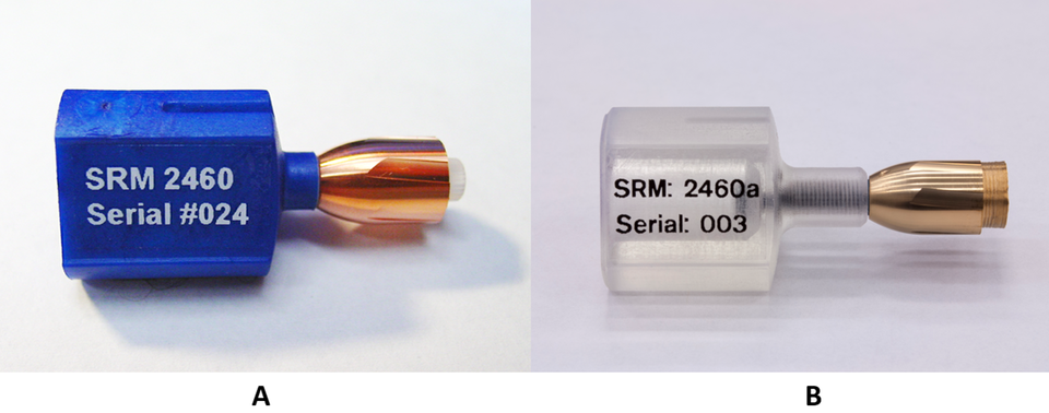
SRM 2460 and 2460a are intended primarily for use as a check standard for forensic laboratories to help verify that the optical equipment for bullet imaging and profiling is operating properly to acquire bullet topography signatures. The standard bullets were designed to have size, shape, color, and material as close as possible to real 9 mm caliber bullets (see Figure 1a). Each standard bullet has six land engraved areas (LEAs). Each LEA contains a bullet signature pattern obtained from a test fired bullet. These reference bullet signatures must be highly repeatable in different axial sections on the same standard bullet, and highly reproducible in a group of standard bullets. A numerically controlled (NC) diamond turning machine was used at NIST for production of the standard bullets. The reference bullet signatures were acquired from six master bullets, one for each LEA, fired by a standardized shooting procedure at the ATF and at the Federal Bureau of Investigation (FBI) Forensic Laboratory. The digitized bullet signatures were used to control the NC diamond turning machine to produce the standard bullets. Figure 1a shows one of the standard bullets produced by this fabrication process. The six reference signatures are shown in Figure 2. Comparison results showed high repeatability and reproducibility of bullet signatures of NIST standard bullets [2].
In 2018, NIST produced the SRM 2460a Standard Bullet Replica to replenish the SRM inventory. SRM 2460a is replicated from the original SRM 2460 Standard Bullet [2]. The polymer replication process enabled NIST to simplify SRM fabrication. The SRM 2460a Standard Bullet Replicas (example shown in Figure 1b) are made of polyurethane coated with a thin layer (≈ 10 nm) of nickel and another thin layer (≈ 20 nm) of gold.
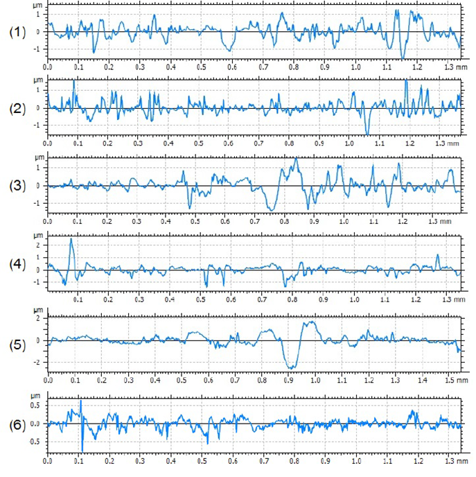
The SRM 2460a virtual bullet signature standards (see Figure 2) are a set of six digitized bullet profile signatures, one for each LEA. The LEA profile signature of a physical SRM 2460a bullet has a certified similarity to the respective virtual bullet signature standard. The virtual bullet signatures provide a comparison reference for the topography measurements of SRM 2460a. The signatures are similar, but not identical, to those of SRM 2460.
The virtual bullet signatures for the SRM 2460 Standard Bullet and SRM 2460a Standard Bullet Replica can be found below and in the Standard Bullet and Cartridge Case section of the NIST Ballistics Toolmark Research Database.
SRM2460 2D Stylus Profiles:
- SRM2460 Master Land 1
- SRM2460 Master Land 2
- SRM2460 Master Land 3
- SRM2460 Master Land 4
- SRM2460 Master Land 5
- SRM2460 Master Land 6
The data are presented in ASCII format. The first column contains the X values in millimeters and the second column contains the Z values in millimeters.
SRM2460a 2D Stylus Profiles:
- SRM2460a Master Land 1
- SRM2460a Master Land 2
- SRM2460a Master Land 3
- SRM2460a Master Land 4
- SRM2460a Master Land 5
- SRM2460a Master Land 6
The data are presented in ASCII format. The first column contains the X values in millimeters and the second column contains the Z values in micrometers.
For more information on the certified values, data processing and analysis, please refer to the SRM2460a Certificate.
STANDARD CARTRIDGE CASE
The SRM 2461 Standard Cartridge Case is a physical standard that provides markings of a fired cartridge case. The SRM is intended primarily for use as a check standard for forensic laboratories to support measurement quality assurance (QA): first, to help verify that the repeatability and reproducibility of cartridge case topography images (three dimensional images) obtained by computerized optical equipment and associated image correlations are within tolerances set by the laboratory; second, to establish ballistics measurement traceability to a set of three master reference artifacts and their measurements from NIST; and third, to facilitate laboratory assessment and accreditation.
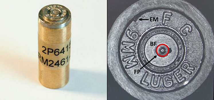
A unit of SRM 2461 consists of a circular electroformed nickel plate, replicated from the head of a fired master cartridge case, which contains a surface topography signature of a breech face impression, a firing pin impression, and an ejector mark. The analyzed breech face impression signature includes a small region of aperture shear marks. The electroformed plate is cemented to a brass cylinder holder (see Figure 3) so that the assembly resembles a real fired cartridge case.
The master cartridge case was fired at the National Laboratory Center of the ATF [2]. The signature reproducibility of the replicated SRM cartridge cases depends on the master cartridge case and on the electroforming process. To ensure that the SRM cartridge cases have virtually the same surface topography signatures, it was necessary to test for differences in the replica surfaces [4]. The results showed that the electroforming process was stable and capable of producing a large number of surfaces that are approximately identical.
The SRM 2461 virtual topography standard consists of topography images obtained from the breech face impression of SRM unit 155, the firing pin impression of SRM unit 153, and the ejector mark of SRM unit 260. The NIST Ballistics Toolmark Research Database contains these topography images with which the user can correlate their topography images obtained from one of the distributed units of SRM 2461. Links to the topography image data are also given below:
- SRM2461-155 Breech Face Master
- SRM2461-155 Breech Face Master_Trimmed
- SRM2461-153 Firing Pin Master
- SRM2461-153 Firing Pin Master_Trimmed
- SRM2461-260 Ejector Mark Master
- SRM2461-260 Ejector Mark Master_Trimmed
For all topography images, the data are presented in ISO 25178-72 X3P format [5]. For more information on this format and ways to read/write data files, please visit http://www.open-fmc.org. Dropouts should be ignored during any type of analysis. The topography images for the breech face and ejector mark were manually trimmed to eliminate irregular edges and headstamp marks from the data to be analyzed. The firing pin impression was trimmed to a circle with a diameter of 500 μm
The filtered topography images result from bandpass filtering to minimize form and waviness and to emphasize the fine roughness features. The conditions of filtering and preprocessing of the raw topography images are described below in the text associated with Figures 4, 5, and 6. The figures also show the raw and filtered topography images of the breech face impression of Unit 155, the firing pin impression of Unit 153, and the ejector mark of Unit 260 measured at NIST.
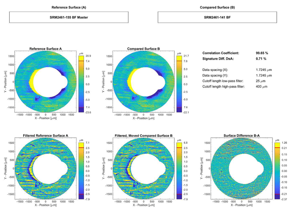
Figure 4 shows an example of the comparison between the topography images of the breech face impression (and some aperture shear) of the SRM reference cartridge case S/N 155 (top, left) and the SRM cartridge case S/N 141 (top, right). The L-Filter nesting index (high-pass filter cutoff length) was 400 μm, and the S-filter nesting index (low-pass filter cutoff length) was 25 μm [6]. At the maximum correlation position, the ACCFMAX [2] is calculated to be 99.65 %. The topography difference Z is also calculated (see bottom, right), and from it, the signature difference Ds [2] is calculated to be 0.71 %.
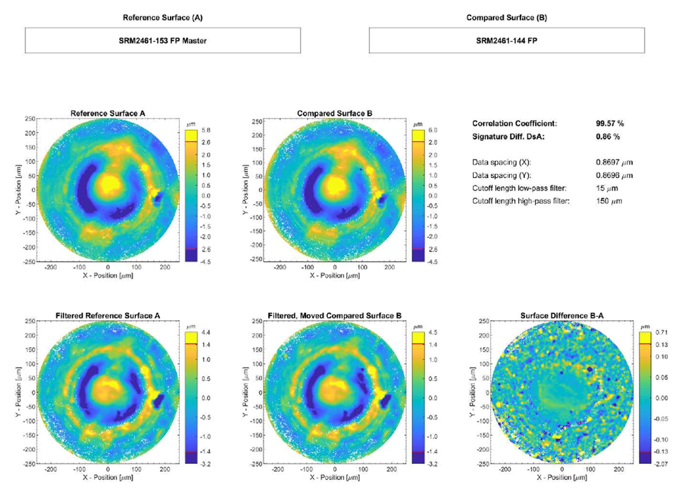
Figure 5 shows an example of the comparison between the topography images of the firing pin impressions of the SRM reference cartridge case S/N 153 (top, left) and the SRM compared cartridge case S/N 144 (top, right). The L-Filter nesting index (high-pass filter cutoff length) was 150 μm, and the S-filter nesting index (low-pass filter cutoff length) was 15 μm [6]. At the maximum correlation position, the ACCFMAX is calculated to be 99.57 %. The topography difference Z is also calculated (see bottom, right), and from it, the signature difference Ds is calculated to be 0.86 %.
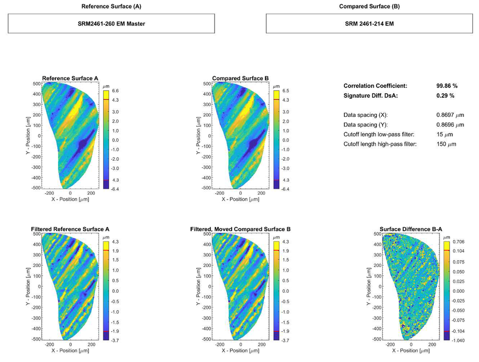
Figure 6 shows an example of the comparison between the topography images of the ejector marks of SRM reference cartridge case S/N 260 (top, left) and the SRM compared cartridge case S/N 214 (top, right). The L-Filter nesting index (high-pass filter cutoff length) was 150 μm, and the S-Filter nesting index (low-pass filter cutoff length) was 15 μm [6]. At the maximum correlation position, the ACCFMAX is calculated to be 99.86 %. The topography difference Z is also calculated (see bottom, right), and from it, the signature difference Ds is calculated to be 0.29 %.
For more information on the certified values, data processing and analysis, please refer to the SRM2461 Certificate.
References
[1] Song, J., Vorburger, T.V., Ballou, S., Thompson, R.M., Yen, J., Renegar, T.B., Zheng, A., Silver, R.M., Ols, M., "The National Ballistics Imaging Comparison (NBIC) Project," Forensic Sci. Int. 216, pp. 168-182 (2012); DOI:10.1016/j.forsciint.2011.09.016.
[2] Song, J., Whitenton, E., Kelley, D., Clary, R., Ma, L., Ballou, S., Ols, M., "SRM 2460/2461 Standard Bullets and Cartridge Cases Project"; J. Res. Natl. Inst. Stand. Technol. 109, pp. 533–542 (2004).
[3] ISO 21920-2; Geometrical product specifications (GPS) - Surface texture: Profile - Part 2: Terms, definitions and surface texture parameters (ISO 21920-2:2021, Corrected version 2022-06)
[4] Song, J., Rubert, P., Zheng, A., Vorburger, T., "Topography measurements for determining the decay factors in surface replication," Measurement Science and Technology 19, 084005 (2008); DOI:10.1088/0957-0233/19/8/084005.
[5] ISO 25178-72:2017/Amd.1:2020; Geometrical Product Specifications (GPS) — Surface Texture: Areal — Part 72: XML file format x3p, Amendment 1; International Organization for Standardization, Geneva, Switzerland (2020).
[6] ISO 25178-2:2021; Geometrical Product Specifications (GPS) — Surface Texture: Areal — Part 2: Terms, Definitions and Surface Texture Parameters; International Organization for Standardization, Geneva, Switzerland (2021).
Contacts
-
(301) 975-4095