
Official websites use .gov
A .gov website belongs to an official government organization in the United States.
Secure .gov websites use HTTPS
A lock (
) or https:// means you’ve safely connected to the .gov website. Share sensitive information only on official, secure websites.
Beamline 7: EUV reflectometry
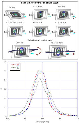
TOP: Sample and detector motions in the large reflectometer chamber. BOTTOM: Reflectance vs. wavelength of a large collection optic.
The NIST/DARPA EUV Reflectometry facility began in the late 1980's to make measurements of the reflectivity of EUV multilayer optics for lithography. Since then, it has undergone major improvements and made a wide range of measurements in addition to EUV reflectivities.
The EUV reflectometry program began on an existing beamline, but in 1993 moved to a separate beamline with a new monochromator specifically designed for reflectivity measurements. This monochromator relies on two variable-line-space plane gratings to give high throughput (around 2 mW at 13 nm) with modest resolution. In 2000 a new sample chamber was installed that is capable of accurately positioning optics up to 35 cm in diameter, 15 cm in thickness, and 40 kg in weight. Recent improvements to the same sample chamber allow for the measurement of optics up to 45 cm in diameter with surface slope up to 35°.
The top figure on the right shows a schematic of the goniometer of our reflectometer. The additional horizontal (x) motion is achieved by shifting the center of motion by 5 cm and relying on 180° roll (Φ) motion to measure two radii rather than one diameter. Although the maximum yaw angle of the sample goniometer is 25°, we can measure slopes greater than 40° by reflecting out of plane using the 55° of detector x motion. Synchrotron radiation is largely horizontally polarized, while the light from plasma sources is unpolarized. Reflecting at roughly equal vertical and horizontal angles allows us to make measurements that simulate unpolarized results. The bottom figure shows the reflectivity as a function of wavelength at several radii on a primary collection optic, which is generally the largest optic in a lithography system. The measurements are all done at the operating angle of incidence, which increases with increasing radius. The drop in peak reflectivity with increasing radius, or increasing angle, is expected due to polarization effects. The Brewster angle for EUV radiation is close to 45°, at which point the p-polarized reflectivity is zero, so the reflectivity for unpolarized light is about half that for s-polarized.
In addition to reflectivity of multilayer optics, beamline 7 has been used to determine many other properties of materials or structures. For example, reflectivity as a function of angle can be used to determine the thickness and optical constants of think films [EUV optical constants], and by use of relay optics, apparatus can be mounted behind the main chamber for purposes such as radiometry.